Photovoltaic charging unit for electric vehicle

A charging unit and electric vehicle technology, applied in the field of solar power generation, can solve the problems that the photovoltaic power generation system does not involve peak-shaving and valley-filling of the power grid, and the energy storage battery cannot obtain electric energy from the city grid, and the energy storage battery cannot obtain electric energy, etc., to achieve High utilization efficiency of solar energy, realization of separate energy conversion, cost calculation and convenient payment

Inactive Publication Date: 2016-04-06
QINGDAO UNIV
View PDF8 Cites 6 Cited by
  • Summary
  • Abstract
  • Description
  • Claims
  • Application Information

AI Technical Summary

Problems solved by technology

The patent [2] does not have an energy storage battery, so it has no peak-shaving and valley-filling effect on the power grid. At the same time, the charging station described in this patent will not work when it is cloudy and the power grid is cut off.
Although the patent [3] has an energy storage battery, it is not connected to the grid, and the energy storage battery cannot obtain electric energy from the city grid; in addition, part of the electric energy generated by the photovoltaic battery described in the patent [3] is stored in the energy storage battery of the street lamp, and the rest of the electric energy is used for electric power. car charging
Patent [4] has an energy storage battery and can be connected to the grid, but the energy storage battery cannot obtain power from the city grid
[0004] In short, none of the patents related to the present invention involve the role of photovoltaic power generation systems in peak-shaving and valley-filling of the power grid; electric vehicle charging stations only meet the basic functions of charging electric vehicles, and do not make full use of the energy storage batteries of electric vehicles. electricity and realize the exchange of electricity and mutual charging of electric vehicles; in addition, there is no simple and feasible operation plan for the billing of photovoltaic charging and discharging.

Method used


Image

  • Photovoltaic charging unit for electric vehicle

Examples


Embodiment Construction

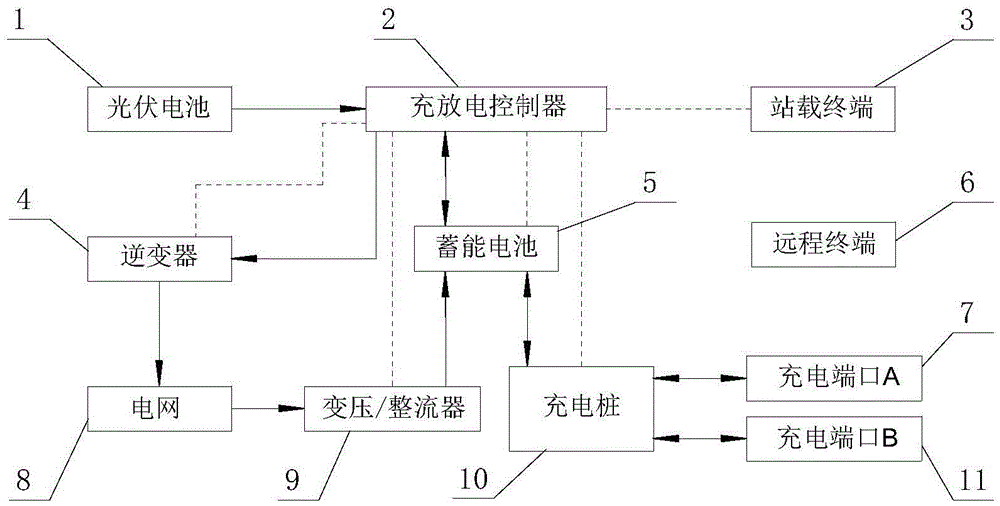
[0015] As shown in the drawings, the main structure of the present invention includes a photovoltaic cell 1 , a charging and discharging controller 2 , a station-mounted terminal 3 , an inverter 4 , an energy storage battery 5 , a remote terminal 6 , a charging pile 10 , and a transformer / rectifier 9 . Photovoltaic cell 1 is a group of series-parallel photovoltaic arrays, which are connected with charge and discharge controller 2 by wires, and convert light energy into DC electric energy and transmit it to charge and discharge controller 2; charge and discharge controller 2 uses digital signals with high-speed processing capabilities The processor DSP is used as the main control chip, connected with the inverter 4 and the energy storage battery 5 through wires, and connected with the inverter 4, transformer / rectifier 9, energy storage battery 5, charging pile 10, and station-mounted terminal 3 through signal lines connection; the inverter 4 is connected with the grid 8 by wires...


PUM


Abstract

The invention discloses a photovoltaic charging unit for an electric vehicle, and belongs to the technical field of solar power generation. The main structure of the photovoltaic charging unit comprises a photovoltaic cell, a charge-discharge controller, a station-mounted terminal, an inverter, an energy storage cell, a remote terminal, a charging port, a charging pile and a transformer/rectifier, wherein the charge-discharge controller is connected with the photovoltaic cell, the station-mounted terminal, the energy storage cell and the inverter separately through corresponding signal lines and wires; the charging pile is connected with the energy storage cell and the charging pile through wires; the station-mounted terminal and the remote terminal are in wireless communication; the input end of the transformer/rectifier is connected to a power grid while the output end of the transformer/rectifier is connected with the energy storage cell; and the input end of the inverter is indirectly connected with the photovoltaic cell through the charge-discharge controller while the output end of the inverter is connected with the power grid for supplying power for the power grid. The photovoltaic charging unit can convert solar energy into electric energy for storage and can be used for peak clipping and valley filling for the power grid so as to charge the electric vehicle or obtain electric energy from the electric vehicle; the electric energy interchange among electric vehicles can be realized; and in addition, remote control and a payment function for multiple kinds of electric charges can be realized as well.

Description

technical field [0001] The invention belongs to the technical field of solar power generation, and relates to a photovoltaic charging unit for an electric vehicle. Background technique [0002] With the development of our country's social economy, the traditional extensive energy consumption has caused huge damage to the ecological environment, and at the same time seriously restricted the sustainable development of the social economy. Nowadays, it is necessary to find a renewable energy source to solve the increasingly serious energy problem. As the most important energy source on the earth, solar energy has attracted more and more attention because of its characteristics of inexhaustibility, environmental protection, safety and reliability. The main way to use solar energy today is to realize photoelectric conversion based on the principle of "photovoltaic effect". At present, the most widely researched and applied solar cells with relatively mature technology are silico...

Claims


Application Information

Patent Timeline
Patent Type & Authority Applications(China)
IPC IPC(8): H02J7/35H02J3/38H02J3/32H02J13/00
CPCH02J3/383H02J3/32H02J7/35H02J13/00B60L53/31B60L53/665Y02E70/30Y04S10/126Y04S30/14Y02E10/56Y02E60/00Y02T90/167Y02T10/70Y02T90/12Y02T10/7072
Inventor 张洪信徐东张铁柱张君楠马永志华青松
Owner QINGDAO UNIV
Why Eureka
Try Eureka