Ultrasonic stress relieving method and system

A technology of stress elimination and ultrasonic, which is applied in the field of ultrasonic stress elimination method and system, can solve the problems that the internal residual stress of the component cannot be eliminated, the resonance of the processed component cannot be excited, and the surface quality of the component is affected, so as to achieve small amplitude, eliminate fixed nodes, The effect of eliminating residual stress

Active Publication Date: 2016-04-13
沈阳赫声装备科技有限公司
View PDF6 Cites 10 Cited by
  • Summary
  • Abstract
  • Description
  • Claims
  • Application Information

AI Technical Summary

Problems solved by technology

[0010] However, the above ultrasonic impact aging equipment has the following limitations:
[0011] 1. It cannot excite the overall resonance of the treated component, but only excites local vibration near the impacted area to eliminate the nearby residual stress; and the depth of the action layer is limited, generally 1-10mm, which cannot eliminate the residual stress inside the entire component
[0012] 2. The ultrasonic vibration system is not directly connected to the processed comp

Method used


Image

  • Ultrasonic stress relieving method and system
  • Ultrasonic stress relieving method and system

Examples


no. 1 example

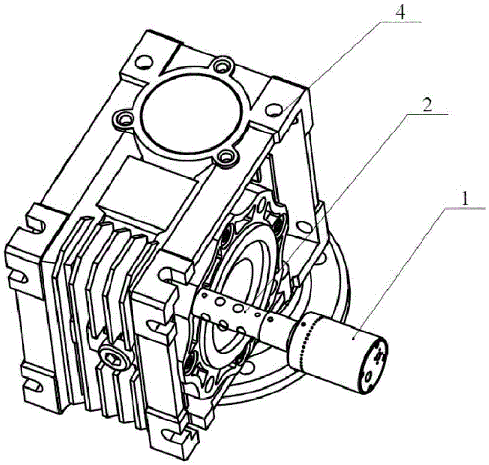
[0082] In this embodiment, the probe 2 is required to be fixedly connected to the processed member 4, and the fixed connection may be bolted, welded, or clamped. The specific probe 2 and ultrasonic transducer 1 should be selected according to the size, material, resonance frequency and other parameters of the component 4 to be processed. Ultrasonic driving power supply must have frequency sweeping and broadband driving functions.

[0083] After the connection of each component is completed, the process of ultrasonic excitation is started. First, use the frequency sweep function of the ultrasonic drive power to sweep around the resonance frequency of the ultrasonic transducer used to find one or more obvious resonance frequencies. Set the excitation frequency output by the ultrasonic drive power supply to a frequency 0%-10% higher than the found resonance frequency, so as to perform sub-resonance excitation. At the same time, start the frequency tracking function of the ultraso...

no. 2 example

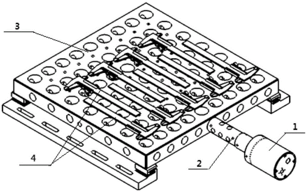
[0087] Vibration base 3 is used to vibrate multiple small components to be processed, such as sensors, gauges and other components that can be processed in batches at one time.

[0088] After the excitation base 3 is connected with the ultrasonic transducer 1 and the probe 2, the member to be processed 4 is connected to the excitation base 3, and the specific method can be bolted connection, pressing plate, welding and so on. After the connection is completed, the ultrasonic excitation treatment of the first embodiment is repeated.

[0089] figure 2 is a perspective view of the ultrasonic vibration system in the second embodiment of the present application. The vibration system consists of an ultrasonic transducer 1, a probe 2, and an excitation base 3. The probe 2 is fixedly connected to the treated member 4, and the ultrasonic drive power supply (not shown) is connected to the ultrasonic transducer 1 through a cable. Specifically, the components can be fixedly connected t...


PUM


Abstract

The invention relates to an ultrasonic stress relieving method. The method comprises the steps that an ultrasonic transducer is connected to a wave guiding rod, the wave guiding rod is fixedly connected to a processed component, and a vibration system is composed of the ultrasonic transducer, the wave guiding rod and the processed component which are sequentially connected; an ultrasonic drive power source carries out frequency scanning on the vibration system, the vibration frequency, closest to the resonance frequency of the ultrasonic transducer and highest in amplitude, of the vibration system is selected as the excitation frequency, and ultrasonic excitation treatment is carried out on the processed component; frequency tracking is carried out on the vibration system, and the resonance state of the vibration system is maintained; and frequency modulation is carried out on the excitation frequency output by the ultrasonic drive power source, at least one resonance modal forming the coupling relationship with a modal corresponding to the resonance frequency of the vibration system is excited, and simultaneous excitation of a plurality of resonance modals is achieved. The invention further relates to an ultrasonic stress relieving system.

Description

technical field [0001] The invention relates to the field of ultrasonic vibration, in particular to an ultrasonic stress elimination method and system. Background technique [0002] Metal components undergo welding, casting, forging, machining and other processes, causing internal lattice deformation, which will inevitably generate residual stress, greatly reduce the ultimate strength and fatigue strength of the component, and even produce cracks and brittle fractures. Due to the relaxation of residual stress during use, the parts are deformed, which greatly affects the size, position accuracy and overall performance of the components. Reducing this internal stress is currently mainly through aging methods. The aging treatment process has been widely used in shipbuilding, metallurgy, machine tools, mining, chemical industry, electric power and other industries, and has received significant economic benefits. [0003] First, the definitions of the terms mentioned in this ar...

Claims


Application Information

Patent Timeline
IPC IPC(8): C21D10/00
CPCC21D10/00
Inventor 赵夙
Owner 沈阳赫声装备科技有限公司
Why Eureka
Try Eureka