Surface modified coating cutting blade and preparation method thereof

A cutting blade and surface modification technology, applied in the field of metal cutting, can solve the problems of insufficient chipping resistance and high deposition temperature, so as to improve the chipping resistance and anti-adhesion performance, improve oxidation resistance, coating Effect of Residual Stress Reduction

Active Publication Date: 2016-04-20
ZHUZHOU CEMENTED CARBIDE CUTTING TOOLS CO LTD
View PDF8 Cites 6 Cited by
  • Summary
  • Abstract
  • Description
  • Claims
  • Application Information

AI Technical Summary

Problems solved by technology

The TiZrCN coating deposited by this patented technology has a higher deposition temperature, and also needs to add a subsequent high-temperature atmosphere heat treatment process, and finally forms a granular coating structure. Under the impact of intermittent processing in milling applications, this The chipping resistance of coated tools with a granular structure is obviously insufficient

Method used


Image

  • Surface modified coating cutting blade and preparation method thereof
  • Surface modified coating cutting blade and preparation method thereof
  • Surface modified coating cutting blade and preparation method thereof

Examples


Embodiment 1

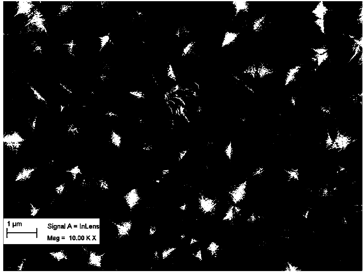
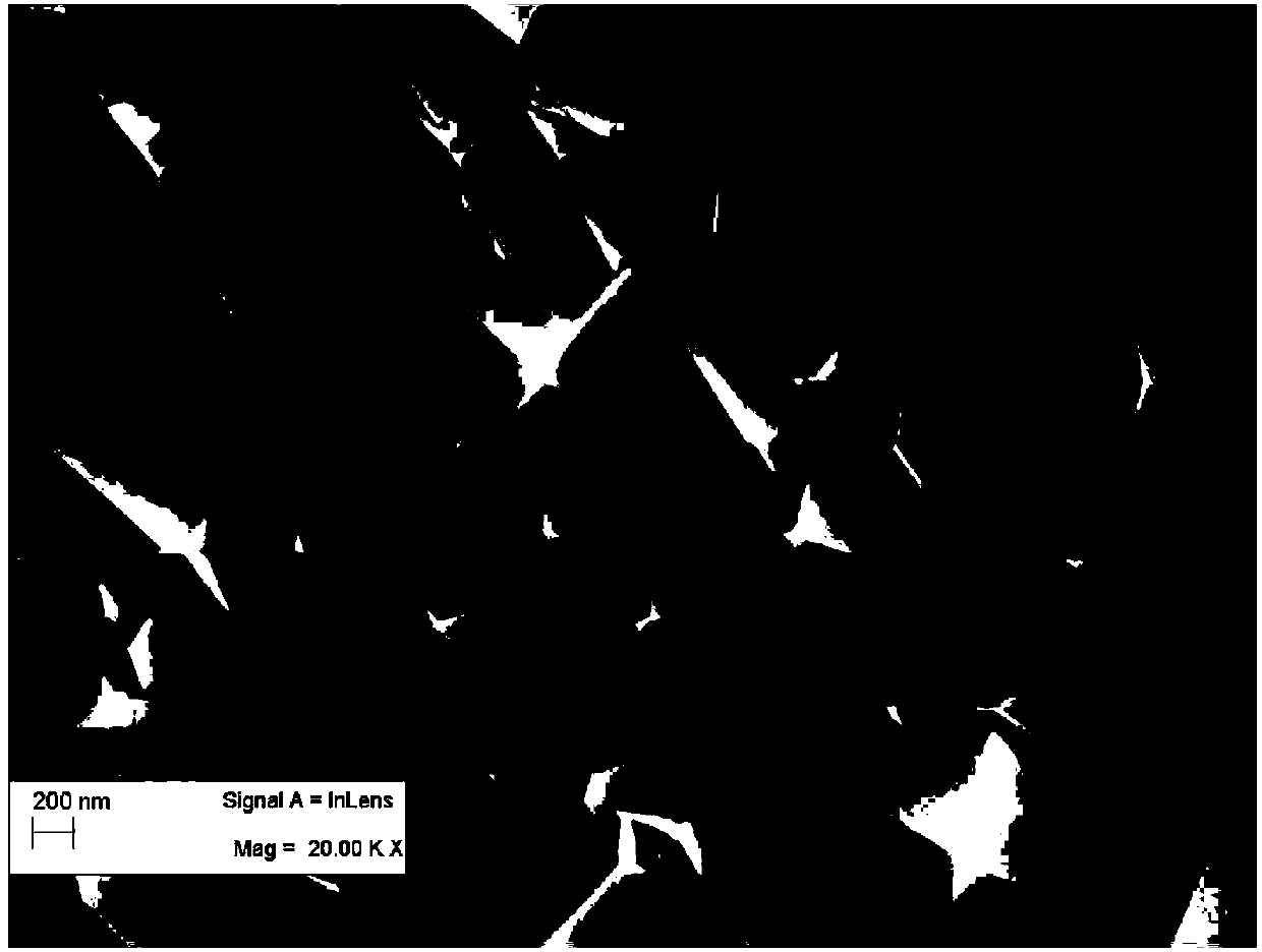
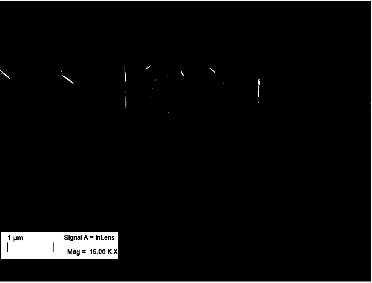
[0046] A surface-modified coating cutting insert of the present invention comprises a cemented carbide insert substrate and a coating deposited on the insert substrate, the coating sequentially includes a TiN layer, an MT-TiZrCN coating, a TiC 0.5 N 0.3 o 0.2 layer, α-Al 2 o 3 layer and Al(Zr) with corundum structure 2 o 3 Modified coating, and Al(Zr) 2 o 3 The modified coating has a strong texture orientation of the (300) crystal plane, and the intensity ratio I(300) / I(110)=2.0 of the orientation crystal plane (that is, the XRD diffraction peaks of the (300) crystal plane and the (110) crystal plane intensity ratio, the same below). The thickness of the TiN layer in the coating is 0.2 μm; the MT-TiZrCN coating is in TiCl 4 -CH 3 CN-HCl-N 2 -H 2 Add ZrCl to the deposition atmosphere system 4 The atmosphere is prepared, the Zr content (atomic percentage, the same below) in the MT-TiZrCN coating is 0.2 at%, the longitudinal surface of the MT-TiZrCN coating is a colum...

Embodiment 2

[0109] A surface-modified coating cutting insert of the present invention comprises a cemented carbide insert substrate and a coating deposited on the insert substrate, the coating sequentially includes a TiN layer, an MT-TiZrCN coating, a TiC 0.6 N 0.3 o 0.1 layer, α-Al 2 o 3 layer and Al(Zr) with corundum structure 2 o 3 Modified coating, and Al(Zr) 2 o 3 The modified coating has a strong texture orientation of (300) crystal plane, and the intensity ratio of the oriented crystal plane is I(300) / I(110)=2.4. The thickness of the TiN layer in the coating is 0.2 μm; MT-TiZrCN coating is in TiCl 4 -CH 3 CN-HCl-N 2 -H 2 Add ZrCl to the deposition atmosphere system 4 Prepared in an atmosphere, the Zr content in the MT-TiZrCN coating is 0.17at%, the longitudinal surface of the MT-TiZrCN coating is a columnar crystal structure, the aspect ratio is ≥ 3, and the thickness of the MT-TiZrCN coating is 5.5 μm; TiC 0 . 6 N 0 . 3 o 0 . 1 The thickness of the layer is 0.5 μm...


PUM

PropertyMeasurementUnit
thicknessaaaaaaaaaa
thicknessaaaaaaaaaa
thicknessaaaaaaaaaa

Abstract

The invention discloses a surface modified coating cutting blade and a preparation method thereof. The cutting blade comprises a blade matrix and a coating deposited on the blade matrix, the coating contains an MT-TiZrCN coating and an outermost Al(Zr)2O3 modified coating with a corundum structure; the Al(Zr)2O3 modified coating has (300) crystal face strong texture orientation, and the strength ratio I(300)/I(110) of the orientation crystal surface is 0.5-2.5. The preparation method includes: sequentially depositing a TiN layer, an MT-TiZrCN coating, a TiCxNyOz layer, an alpha-Al2O3 layer and an Al(Zr)2O3 modified coating on the blade matrix, thus obtaining the surface modified coating cutting blade. The surface modified coating cutting blade provided by the invention has excellent heat resistance, anti-tipping performance and anti-adhesion performance, and is suitable for general milling processing and other aspects of steel and stainless steel.

Description

technical field [0001] The invention belongs to the field of metal cutting, and in particular relates to a surface-modified coating cutting blade and a preparation method thereof. Background technique [0002] The surface of modern CVD (chemical vapor deposition) coated cutting inserts generally contains two main wear-resistant layers, MT-TiCN coating and Al 2 o 3 Coating to provide sufficient flank wear and crater wear resistance for coated cutting inserts, while ensuring a certain heat resistance. However, when CVD-coated cutting inserts are used in steel milling applications, especially when milling highly viscous workpiece materials such as stainless steel, the cutting edge of the insert is subject to intermittent impact, the cutting temperature continues to change, and the viscous chip material adheres to the insert surface. Chipping of the blade and peeling off of the surface coating occur. [0003] It is well known that relative to Al 2 o 3 For the MT-TiCN coatin...

Claims


Application Information

Patent Timeline
Patent Type & Authority Applications(China)
IPC IPC(8): C23C16/34C23C16/36C23C16/40B32B9/04
Inventor 李秀萍陈响明王社权刘王平周文豪
Owner ZHUZHOU CEMENTED CARBIDE CUTTING TOOLS CO LTD
Why Eureka
Try Eureka