Plasma 3D (three-dimensional) fast forming equipment and method for rollers

A molding equipment, plasma technology, applied in the field of ion 3D rapid prototyping equipment and molding, can solve the problems of cracking, complex structure, scrapping and so on

Inactive Publication Date: 2016-04-27
SINOADDITIVE MFG EQUIP CO LTD
View PDF11 Cites 5 Cited by
  • Summary
  • Abstract
  • Description
  • Claims
  • Application Information

AI Technical Summary

Problems solved by technology

[0004] First, when the centrifugal casting method is used to manufacture rolls, molten steel smelting is first required. During the smelting process, problems such as spalling of ladle refractories and insufficient deoxidation of molten steel and insufficient slag removal may cause pollution to molten steel, resulting in reduced performance or scrapping of the rolls;
[0005] Second, the elements in the centrifugal casting process are likely to cause segregation due to different specific gravity, resulting in a decrease in the performance of the roll;
[0006] Third, centrifugally cast rolls need to be heat treated after casting, the process is complex, and the existing heat treatment system is likely to cause microcracks, cracks or even scrapping of the rolls
But at present, there are three main problems in the selective electron beam rapid prototyping technology:

Method used


Image

  • Plasma 3D (three-dimensional) fast forming equipment and method for rollers
  • Plasma 3D (three-dimensional) fast forming equipment and method for rollers
  • Plasma 3D (three-dimensional) fast forming equipment and method for rollers

Examples


Embodiment 1

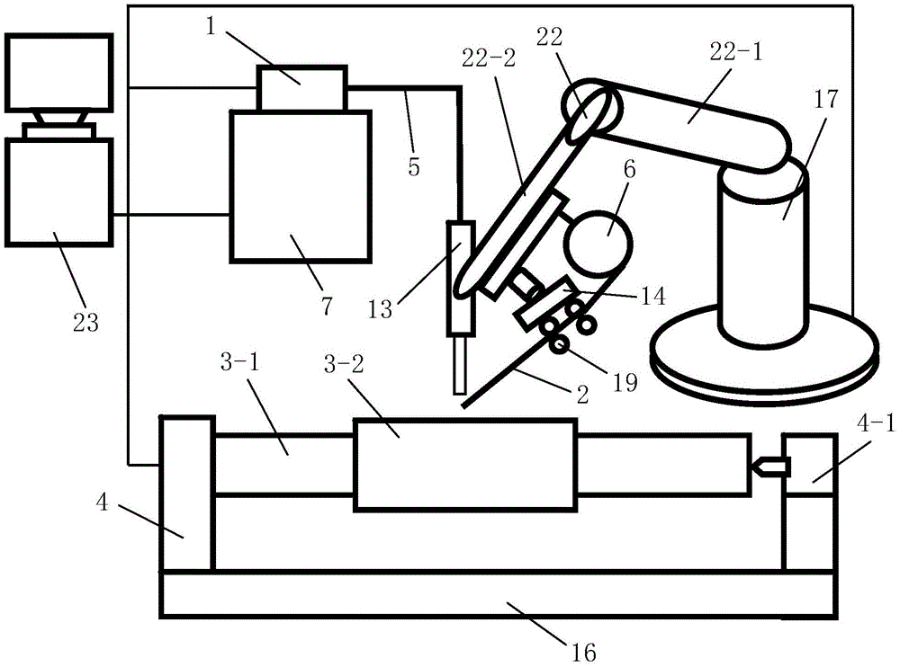
[0088] Such as figure 1 A roll plasma 3D rapid prototyping equipment shown is composed of a monitoring system, a plasma beam processing system and a horizontal printing platform for placing a roll to be formed. The roll to be formed includes a roll core 3-1 and is arranged on the roll core 3 - The outer layer 3-2 of the roller body outside the middle part, the outer layer 3-2 of the roller body is coaxially arranged with the roller core 3-1; the horizontal printing table includes a horizontal support mechanism 16 and is fixedly installed on the horizontal support mechanism 16 And the horizontal rotation mechanism 4 that drives the roller core 3-1 to rotate around its central axis, the horizontal rotation mechanism 4 is located above the horizontal support mechanism 16, the roller core 3-1 is arranged horizontally and installed on the horizontal rotation mechanism 4 superior.

[0089]The plasma beam processing system consists of a plasma generator equipped with a shower head a...

Embodiment 2

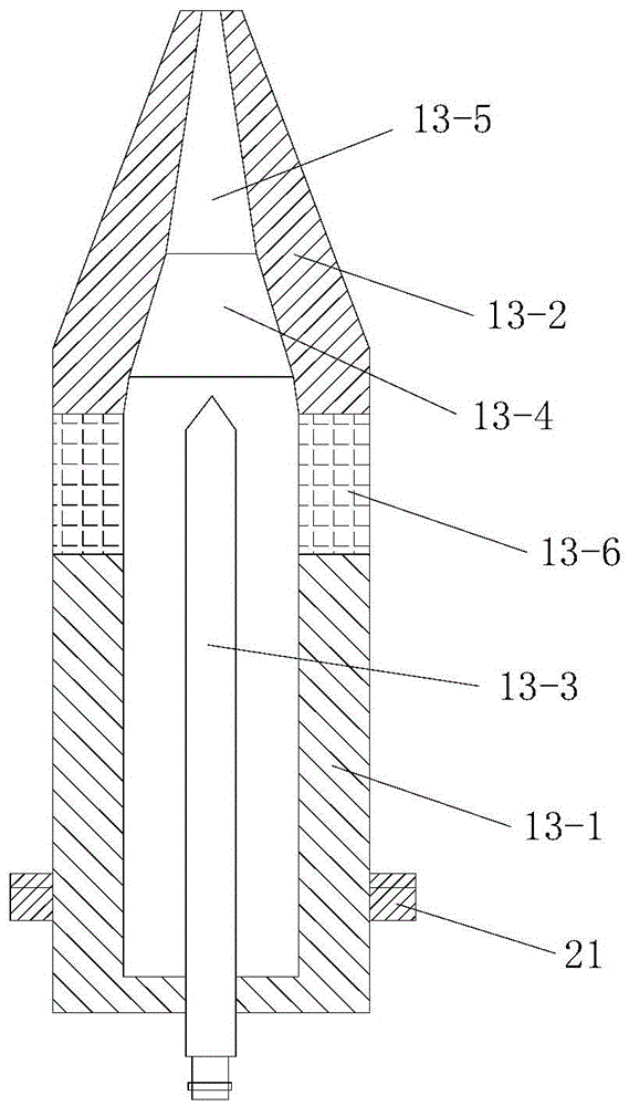
[0203] In this example, if Figure 7 As shown, the difference between the roll plasma 3D rapid prototyping equipment used and the embodiment 1 is that the angle between the nozzle 13-5 and the central axis of the gun body 13-1 is 30°-45°.

[0204] In this way, after changing the direction of the plasma beam through the nozzle 13-5, the thermal load impact of the plasma jet on the anode nozzle 13-2 can be effectively reduced, and the anode ablation condition is improved.

[0205] In this embodiment, the structure, connection relationship and working principle of the remaining parts of the roll plasma 3D rapid prototyping equipment are the same as those in Embodiment 1.

[0206] In this embodiment, the roll plasma 3D rapid prototyping method adopted is the same as that in Embodiment 1.


PUM

PropertyMeasurementUnit
Diameteraaaaaaaaaa
Heightaaaaaaaaaa

Abstract

The invention discloses plasma 3D (three-dimensional) fast forming equipment and method for rollers. The equipment is composed of a monitoring system, a plasma beam machining system and a horizontal printing platform for holding to-be-formed rollers; the plasma beam machining system comprises a plasma generator, a gas supply device, a wire conveying device used for continuously conveying out machined wires and a printing position adjustment device; the monitoring system comprises a position adjustment controller, a temperature detection unit, a distance detection unit, a printing distance adjustment controller and a rotation controller, and the temperature detection unit and the printing distance adjustment controller, form a temperature control device. The method includes the steps of 1, three dimensional model acquisition and hierarchical slicing, 2, scanning path filling, 3, printing path acquisition and 4, printing layer by layer from inside to outside. The equipment and method is reasonable in design, simple to operate, high in forming efficiency and good in using effect, and the formed rollers are high in quality as the forming process is conducted directly under the atmospheric environment.

Description

technical field [0001] The invention belongs to the technical field of rapid prototyping, and in particular relates to a roll plasma 3D rapid prototyping equipment and a prototyping method. Background technique [0002] The roll is an important part of the rolling mill in the rolling mill. It uses the pressure generated by a pair or a group of rolls to roll and roll the steel. It is mainly subjected to dynamic and static loads, wear and temperature changes during rolling. The roll mainly includes a core (also called a roll core, including a roll shaft and a roll neck) and an outer layer of a roll body (also called an outer layer or a working layer) coaxially arranged outside the core. The outer layer of the roll body and the core of the composite roll are made of different materials. The two materials are metallurgically bonded. The outer layer of the roll body is the working layer and the outer surface is the roll surface. The roll can meet the wear resistance of the roll ...

Claims


Application Information

Patent Timeline
IPC IPC(8): B22F3/105B22F5/00B33Y10/00B33Y30/00B33Y50/02
CPCB22F5/00B22F10/00B22F10/322B22F12/226B22F10/25B22F12/90B22F12/41B22F12/70Y02P10/25
Inventor 华云峰程国君郝勇魏志宇
Owner SINOADDITIVE MFG EQUIP CO LTD
Why Eureka
Try Eureka