Water-cooled-wall multi-stage stair type incinerator

A stepped, water-cooled wall technology, applied in the field of incinerators, can solve the problems of destroying the fluidized state, good air tightness, high investment cost, and achieve the effect of strong adaptability

Inactive Publication Date: 2016-05-04
JIANGSU QUANNENG ELECTROMECHANICAL EQUIP ENG LTD BY SHARE LTD
View PDF6 Cites 0 Cited by
  • Summary
  • Abstract
  • Description
  • Claims
  • Application Information

AI Technical Summary

Problems solved by technology

Among them: the fluidized bed incinerator has strict requirements on the particle size of the material (particle size is less than 50mm), the complexity of the waste pretreatment process will increase the possibility of secondary pollution, and some low melting point substances in the waste will be in the fluidized bed It is in a molten state within the working temperature range, sticks to the bed material, and destroys the fluidized state. Therefore, this kind of incinerator is not very adaptable to the burning garbage, and the combustion is often not very sufficient; although the technology of the rotary kiln incinerator is mature, The operation is simple and flexible, and it is suitable for treating solid and liquid wastes of various shapes, but its disadvantages are high mechanical technical requirements, large investment, and high maintenance costs; low thermal efficiency; the entire system requires good air tightness, which is difficult for operation. Difficulties in operation; solid waste has a strong abrasive effect on refractory materials, and the service life is short; centralized shutdown and maintenance takes a long time; for small and medium-sized devices with a processing scale of less than 6-8t / d, the investment cost is high and investment recovery low rate

Method used


Image

  • Water-cooled-wall multi-stage stair type incinerator

Examples


Embodiment Construction

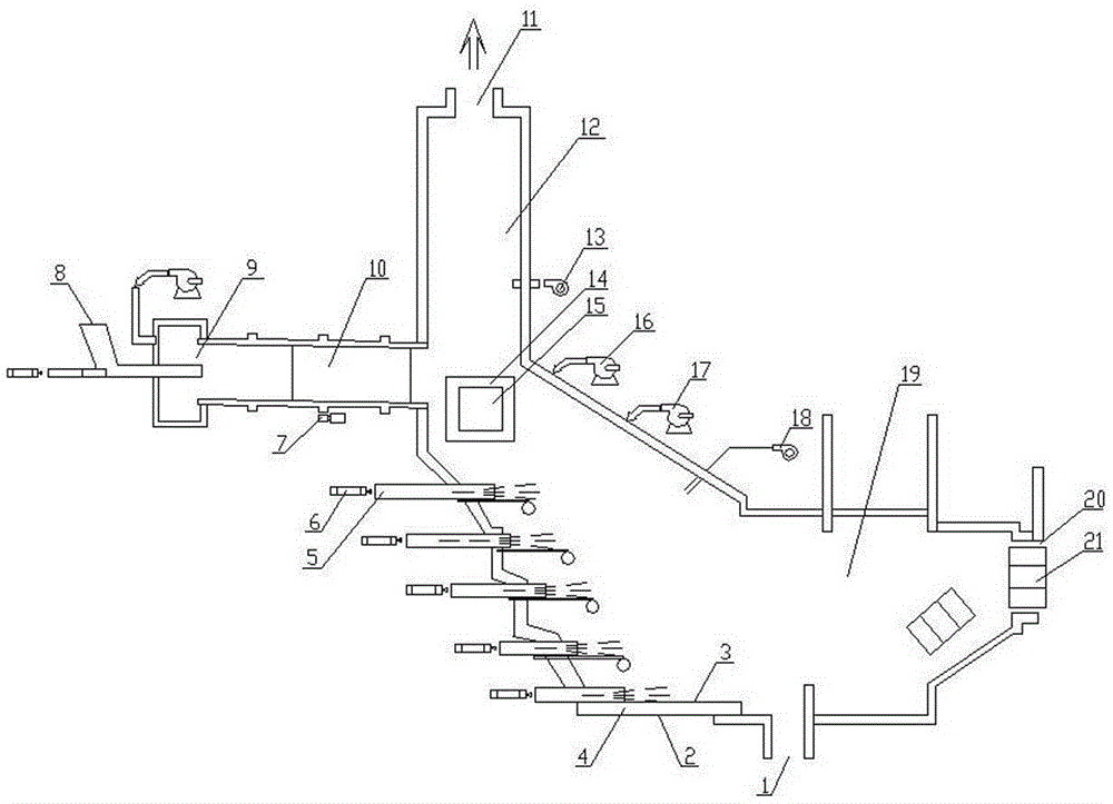
[0016] Such as figure 1 As shown, the water-cooled wall multi-stage stepped incinerator of the present invention includes a furnace body, the furnace body includes an inner wall 3 and an outer wall 2, and a gap 4 is left between the inner wall 3 and the outer wall 2 for cooling water circulation. There are flue gas outlets 11 and slag outlets 1 on the upper and bottom parts of the furnace body respectively, and there is a feeding port 9 on the furnace wall on the side in the middle of the height direction of the furnace body. Combustion chamber 19, that section of furnace body above feed port 9 constitutes secondary combustion chamber 12. A rotary kiln feed device 10 and a feed device 8 are sequentially connected to the feed port 9 . The part of the furnace body where the primary combustion chamber 19 is located is arranged in an inclined shape, and its lower side furnace wall is processed into a multi-stage step shape, and a stirring device is provided on the horizontal dire...


PUM


Abstract

The invention discloses a water-cooled-wall multi-stage stair type incinerator which comprises an incinerator body. A smoke outlet and a slag outlet are formed in the upper portion and the bottom of the incinerator body. A feed inlet is formed in the incinerator wall on one side of the incinerator body. A primary combustion chamber and a secondary combustion chamber are arranged on the portions, below the feed inlet and above the feed inlet, of the incinerator body respectively. A rotary kiln feeding device and a feeding device are arranged on the feed inlet. The incinerator is characterized in that the portion, where the primary combustion chamber is arranged, of the incinerator body is obliquely arranged, at least two sections of lower side incinerator walls of the incinerator body are arranged and in a stair shape, and each section of stair-shaped incinerator wall is provided with a stirring device in the horizontal direction. The upper side incinerator wall where the primary combustion chamber is located is sequentially provided with a combustion draught fan, a stirring draught fan and a primary burner from top to bottom. The combustion draught fan, the stirring draught fan and the primary burner are communicated with the primary combustion chamber. The outer side of the incinerator wall where the secondary combustion chamber is located is provided with a secondary burner communicated with the secondary combustion chamber. The incinerator is high in adaptability to burning garbage and sufficient in incineration, and the incinerator body is resistant to impact, long in service life, low in investment and operation cost, low in maintenance cost and high in heat efficiency. The incinerator is suitable for waste incineration disposal.

Description

technical field [0001] The invention relates to an incinerator. Specifically, it is a water-cooled wall multi-stage stepped garbage incinerator used for incinerating waste. Background technique [0002] At present, the incinerators used for waste incineration are mainly fluidized bed incinerators, rotary kiln incinerators, etc. Among them: the fluidized bed incinerator has strict requirements on the particle size of the material (particle size is less than 50mm), the complexity of the waste pretreatment process will increase the possibility of secondary pollution, and some low melting point substances in the waste will be in the fluidized bed It is in a molten state within the working temperature range, sticks to the bed material, and destroys the fluidized state. Therefore, this kind of incinerator is not very adaptable to the burning garbage, and the combustion is often not very sufficient; although the technology of the rotary kiln incinerator is mature, The operation i...

Claims


Application Information

Patent Timeline
Patent Type & Authority Applications(China)
IPC IPC(8): F23G5/44F23G5/02F23G5/46
CPCF23G5/444F23G5/02F23G5/46
Inventor 张建平杭兵
Owner JIANGSU QUANNENG ELECTROMECHANICAL EQUIP ENG LTD BY SHARE LTD
Why Eureka
Try Eureka