

Real-time measurement method and device for deformation of formed part in additive manufacturing process
An additive manufacturing and real-time measurement technology, applied in the field of additive manufacturing, can solve the problems of large error, low measurement accuracy, lack of experimental verification of deformation of formed parts, etc., and achieve the effect of large scale
- Summary
- Abstract
- Description
- Claims
- Application Information
AI Technical Summary
Problems solved by technology
Method used
Image

Examples
Embodiment Construction
[0031] The present invention will be further described in detail below in conjunction with specific embodiments, which are explanations of the present invention rather than limitations.
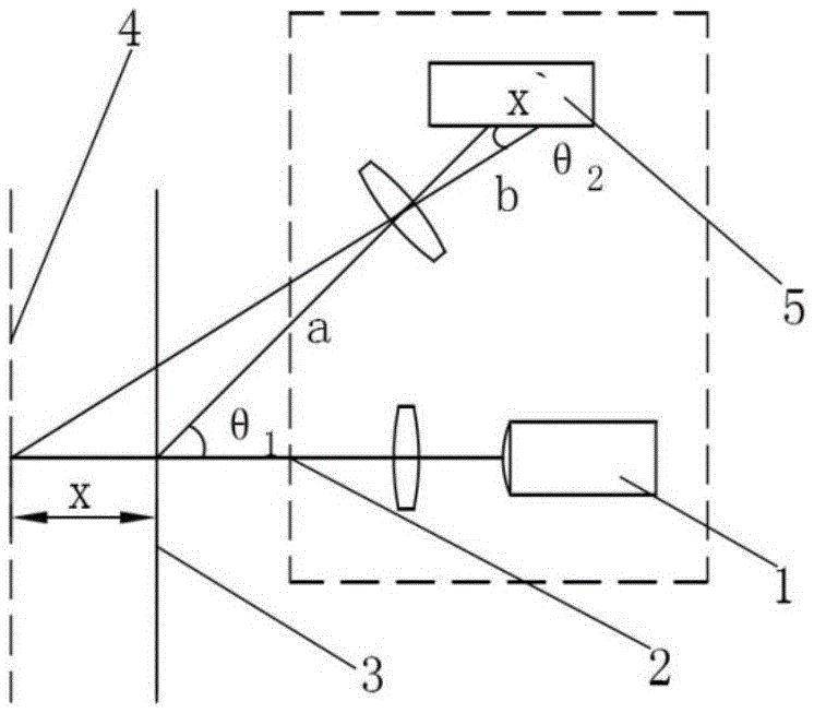
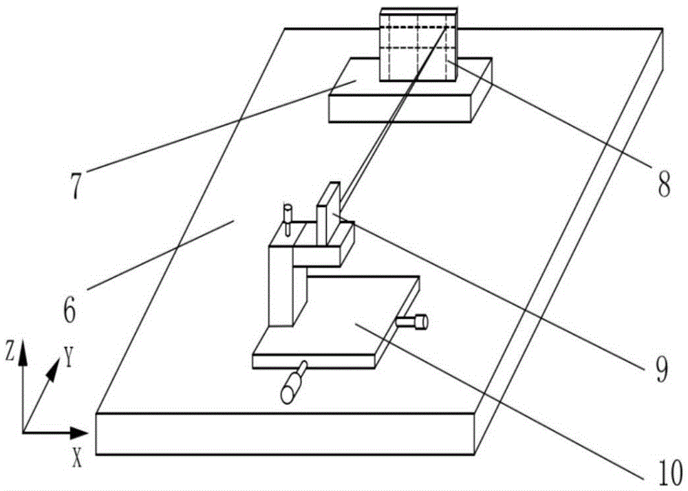
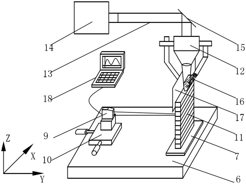
[0032] The purpose of the invention is to solve the problem of real-time measurement of the deformation of formed parts in the process of high-energy beam additive manufacturing. With the development of high-energy beam additive manufacturing, the deformation problem of parts during the forming process has not been effectively solved for a long time, which seriously affects the progress of the forming process and the final forming quality of the formed parts. If some means can be used Real-time monitoring of the deformation behavior of the formed part, through the understanding of the deformation behavior of the formed part under different conditions, including the size of the formed part, the simplicity of the shape of the formed part, the wall thickness of the formed part, the forming method...
PUM
 Abstract
Description
Claims
Application Information