Active thermal optimization control method and device of electromobile driving system

A drive system, electric vehicle technology, applied in electric vehicles, AC motor control, control systems, etc., can solve problems such as limiting the performance of the drive system to maximize operation, reducing system reliability, and the inability of fans to meet the requirements of high reliability.

Active Publication Date: 2016-05-11
HUNAN UNIV
View PDF10 Cites 24 Cited by
  • Summary
  • Abstract
  • Description
  • Claims
  • Application Information

AI Technical Summary

Problems solved by technology

It has some limitations and deficiencies: ① The DC side needs to be connected in parallel with a capacitor bank with high performance and high ripple effective value
Existing inverters mostly adopt passive thermal management. Taking the worst working environment (when the motor is locked) as the reference environment, set fixed current / torque / power values ​​in the system control, leaving a large Although the safety margin ensures that the temperature of the device remains within a safe range, it inevitably reduces the short-term overload performance, ignores the impact of real-time temperature on the system, and limits the maximum performance of the drive system; Fourth, the existing improvement Drivetrain reliability approach focuses on enhancing thermal circulation with faster coolant / air velocity or larger radiators to improve cooling
However, increasing the flow rate of coolant will increase the volume and cost of the system. At the same time, the fan cannot meet the high reliability requirements of modern vehicles. The increased cooling and ventilation equipment will increase the number of control objects in the drive system, and at the same time bring additional heat sources and increase costs. , which reduces the system reliability

Method used


Image

  • Active thermal optimization control method and device of electromobile driving system
  • Active thermal optimization control method and device of electromobile driving system
  • Active thermal optimization control method and device of electromobile driving system

Examples


Embodiment Construction

[0053] The specific embodiments of the invention will be further described below in conjunction with the accompanying drawings. The following examples are only used to illustrate the technical solution of the present invention more clearly, but not to limit the protection scope of the present invention.

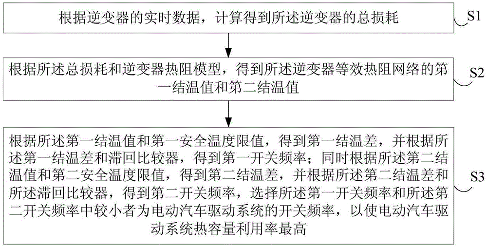
[0054] figure 1 It shows a schematic flowchart of an active thermal optimization control method for an electric vehicle drive system provided in this embodiment, including:

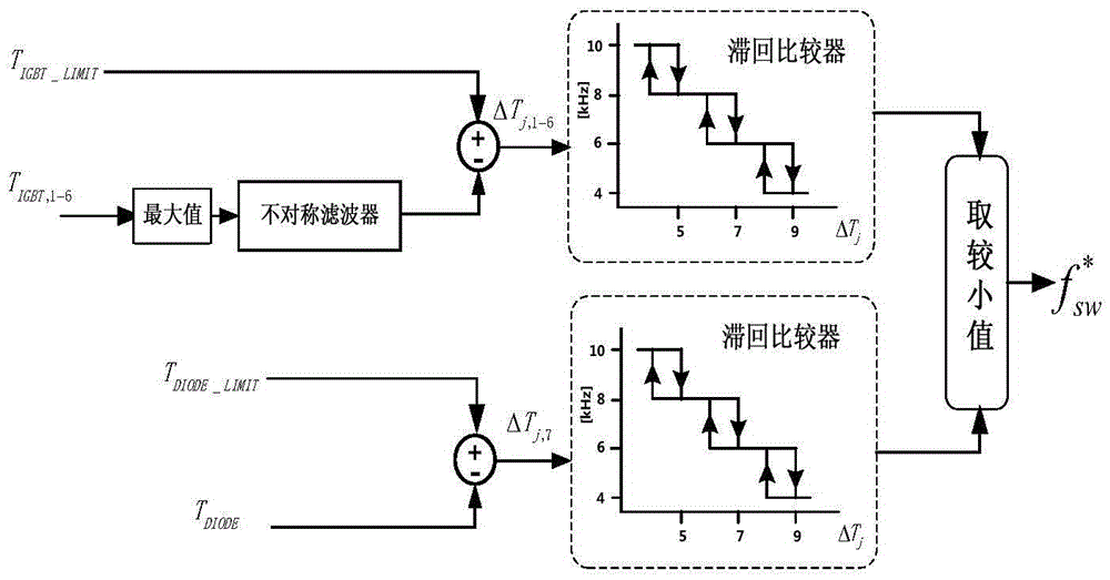
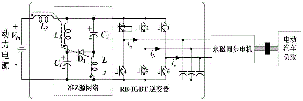
[0055] S1. Calculate the total loss of the current-mode quasi-Z-source inverter according to the real-time data of the current-mode quasi-Z-source inverter;

[0056] S2. Obtain the first junction temperature value and the second junction temperature value of the equivalent thermal resistance network of the current-mode quasi-Z-source inverter according to the total loss and the thermal resistance model of the current-mode quasi-Z-source inverter;

[0057] S3. Obtain the first junction temperature diffe...


PUM


Abstract

The invention discloses an active thermal optimization control method and device of an electromobile driving system. The method comprises the following steps of calculating total loss of an inverter according to real-time data of the inverter; obtaining a first junction temperature value and a second junction temperature value of an inverter equivalent thermal resistance network according to the total loss and an inverter thermal resistance model; obtaining a first switching frequency according to the first junction temperature value, a first safe temperature limit value and a hysteresis comparator; simultaneously obtaining a second switching frequency according to the second junction temperature value, a second safe temperature limit value and the hysteresis comparator; and selecting the smaller one of the first switching frequency and the second switching frequency as the switching frequency of the electromobile driving system. According to the method, a current-type quasi-Z source inverter is adopted, and the problem of active thermal optimization control of the inverter on an actual heat constraint condition is solved by adjusting the shoot-through duty ratio of the inverter, the switching frequency and a control signal output from a space vector pulse width modulator.

Description

technical field [0001] The invention relates to the field of electric vehicle drive systems, in particular to an active thermal optimization control method and device for the electric vehicle drive system. Background technique [0002] With the urgent need for the industrialization of electric vehicles and the advancement of motor drive system technology, electric vehicles have increasingly stringent requirements for high performance, high density and high reliability of the drive system. Great challenges coexist. The inherent defects of the traditional voltage source inverter make it difficult for this topology to meet future requirements for high performance and high reliability. [0003] Reliability, packaging and integration, and thermal management are the three most challenging technical areas in the future power electronics field. In the application of electric vehicles, the ever-increasing demand for power density of the drive system and the challenges of the therma...

Claims


Application Information

Patent Timeline
Patent Type & Authority Applications(China)
IPC IPC(8): H02P27/08B60L11/18
CPCB60L50/50H02P27/08Y02T10/64Y02T10/70Y02T10/72
Inventor 刘平孙千志黄守道冯垚径李慧敏罗德荣姜燕李梦迪
Owner HUNAN UNIV
Why Eureka
Try Eureka