High-precision 3D printing device based on SLA technology

A 3D printing, high-precision technology, applied in the direction of additive processing, etc., can solve the problems that affect the final quality of the product, the surface of the polymer is rough, and the precision cannot be very high, so as to eliminate the influence of high temperature, improve the bonding force between layers, eliminate The effect of step marks

Active Publication Date: 2016-05-25
苏州光宝科技股份有限公司
View PDF6 Cites 7 Cited by
  • Summary
  • Abstract
  • Description
  • Claims
  • Application Information

AI Technical Summary

Problems solved by technology

[0005]1. The PLC drives and controls the lifting of the working platform to control the liquid level and layer thickness. Since it is a mechanical lifting mechanism, its precision cannot be very high, so it is difficult to print balls. The step mark is still relatively serious on the curved surface;
[0006]2. Because the photosensitive resin of the upper layer is mixed with the cured polymer surface of the lower layer, if a high-intensity laser is used to carry out the polymerization reaction, high temperature will be generated, and these high temperatures cannot be timely Dispersion will make the surface of the polymer rough, resulting in insufficient bonding between layers, which will affect the final quality of the product;
[0007]3. Due to the above 2 reasons, the current equipment uses low-intensity laser to carry out the polymerization reaction, and the curing is often incomplete during the printing process, which also affects the final quality of the product

Method used


Image

  • High-precision 3D printing device based on SLA technology
  • High-precision 3D printing device based on SLA technology

Examples


Embodiment

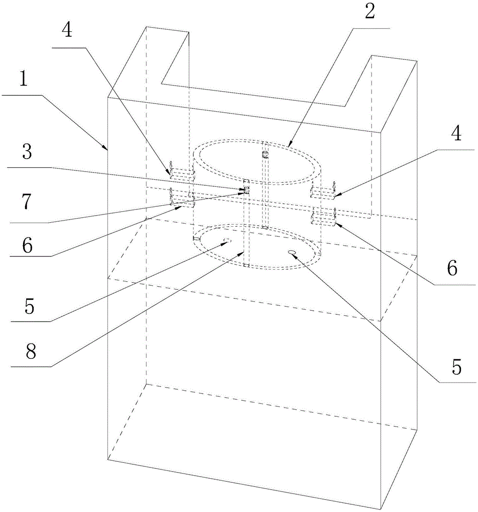
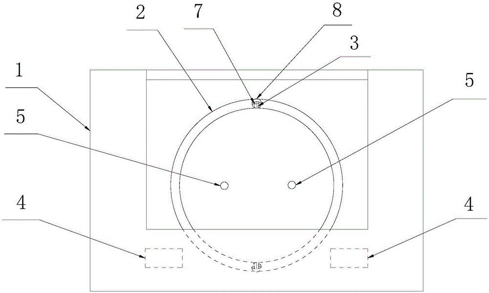
[0029] Example: Combine figure 1 with figure 2 Shown is the specific implementation of the high-precision 3D printing device based on SLA technology provided by the present invention. 2. The upper laser scanning head mechanism (omitted in the figure) also includes a PLC controller (omitted in the figure) electrically connected to the laser scanning head mechanism.

[0030] The improvement in this embodiment is that two longitudinal limiting grooves 8 are provided on the inner side wall of the photocuring working cylinder groove 2, and one side of each longitudinal limiting groove 8 passes through the opening and the light curing working cylinder groove 2. The lumen is connected. Floats 7 are provided in the two longitudinal limiting grooves 8, and each float 7 is provided with a photosensitive resin injection port 3, and the inner cavity of each float 7 is connected to the photosensitive resin injection pump 4 through a pipeline. The photosensitive resin storage cont...


PUM


Abstract

The invention discloses a high-precision 3D printing device based on an SLA technology. The high-precision 3D printing device comprises a device table, a photocuring working barrel groove formed in the device table, a laser scanning head mechanism and a PLC. At least one photosensitive resin injection opening is formed in the portions, of the same horizontal height, of the inner side wall of the photocuring working barrel groove. The photosensitive resin injection openings are connected with a photosensitive resin storing container through pipelines and a photosensitive resin topping-up pump. At least one bearing medium injection opening is formed in the position, lower than the photosensitive resin injection openings, of the inner side wall of the barrel groove. The bearing medium injection openings are connected with a bearing medium storing container through pipelines and a bearing medium topping-up pump. The photosensitive resin topping-up pump and the bearing medium topping-up pump are electrically connected with the PLC. Photosensitive resin floats on the surface of a bearing medium, while high polymer formed after the photosensitive resin is cured is sunken into the bearing medium. The printing device is high in printing precision, transition of printing cambered surface trails is smooth, the photosensitive resin is cured completely, and curing bonding force among layers is large.

Description

Technical field [0001] The invention involves a high -precision 3D printing device based on SLA technology. Background technique [0002] SLA technology, also known as optical solidification and fast forming technology, is the principle of computer -controlled laser beams to scan the surface of light -sensitive resin as raw materials.A thin layer of the product.The workbench moves a thick layer of distance in order to solidify the surface of the resin and apply a new layer of liquid resin to the next layer of scanning and processing, so that the prototype of the entire product is completed. [0003] Since the optical aggregation reaction is based on the role of light and not the heat -based effect, 3D printing equipment based on SLA technology only requires low -power laser sources at work.In addition, because there is no thermal diffusion, and the chain reaction can well control the guarantee that the polymerization reaction does not occur outside the laser point, so the process...

Claims


Application Information

Patent Timeline
IPC IPC(8): B29C67/00B33Y30/00
Inventor 郭勇夏志云钱咏梅
Owner 苏州光宝科技股份有限公司
Why Eureka
Try Eureka