Petroleum hydrocarbon adsorption desulfurization method

A technology for adsorption desulfurization and petroleum hydrocarbons, which is applied in the petroleum industry, hydrocarbon oil treatment, hydrogenation process, etc. It can solve the problems of increasing energy consumption and wasting hydrogen, and achieve the effects of saving energy consumption, reducing wear and tear, and high production efficiency

Active Publication Date: 2016-06-01
CHINA PETROLEUM & CHEM CORP +1
View PDF4 Cites 3 Cited by
  • Summary
  • Abstract
  • Description
  • Claims
  • Application Information

AI Technical Summary

Problems solved by technology

Metal components undergo unnecessary regeneration and reduction, which wastes a lot of hydrogen and increases energy consumption

Method used


Image

  • Petroleum hydrocarbon adsorption desulfurization method
  • Petroleum hydrocarbon adsorption desulfurization method
  • Petroleum hydrocarbon adsorption desulfurization method

Examples


preparation example Construction

[0052] The preparation method of the desulfurization adsorbent in the embodiment of the present invention is as follows:

[0053] Will be used as 4.8Kg pseudo-boehmite (production of Shandong Aluminum Factory, Al 2 o 3Content 62.0% by weight), 7Kg of ZnO (Beijing Beihua Fine Chemicals Co., Ltd., chemically pure) and 22.8Kg water mixed beating, add 600g hydrochloric acid (concentration 36% by weight, Beijing Beihua Fine Chemicals Co., Ltd., chemically pure reagent ), the resulting colloid was spray-dried to form particles with a size of 1 mm, and then calcined at 550° C. for 2 h to obtain a microspherical catalyst Cat1. Similarly, catalysts Cat2, Cat3 and Cat4 were obtained, and their compositions are shown in Table 3.

[0054] Table 1

[0055] Liquefied gas raw material properties

Liquefied gas composition, v%

propane

42.64

Acrylic

18.64

butane

21.18

Normal and isobutylene

14.2

Butene-2

3.1...

Embodiment 1

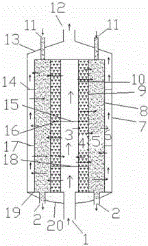
[0068] use as figure 1 The radial flow moving bed reactor shown uses the catalytic cracking gasoline raw material in Comparative Example 1, the pressure is 3.0MPa, and the hydrogen-to-oil ratio is 0.3Nm 3 / m 3 , the reaction temperature is 410°C, and the reaction weight hourly space velocity is 4h -1 , The adsorbent regeneration temperature is 550 °C. The catalyst fixed bed is filled with hydrodesulfurization catalyst RSDS-21, and the catalyst moving bed uses desulfurization adsorbent Cat-1. Product properties and hydrogen consumption are shown in Table 4.

Embodiment 2

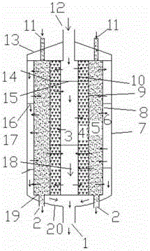
[0070] use as figure 2 The radial flow moving bed reactor shown uses the same FCC gasoline raw material as in Comparative Example 1, the catalyst fixed bed is filled with hydrodesulfurization catalyst RSDS-21, and the catalyst moving bed uses desulfurization adsorbent Cat-2. The pressure of the radial flow moving bed reactor is 2MPa, and the hydrogen-oil ratio is 0.5Nm 3 / m 3 , The reaction temperature is 440°C, and the regeneration temperature of the adsorbent is 550°C. Product properties and hydrogen consumption are shown in Table 4.


PUM

PropertyMeasurementUnit
particle sizeaaaaaaaaaa

Abstract

A petroleum hydrocarbon adsorption desulfurization method adopts a moving bed radial flow reactor. The reactor is divided into a fluid feed channel, a catalyst fixed bed layer, a catalyst moving bed layer and a fluid discharge channel in the radial direction from outside to inside or from inside to outside; the top and the bottom of the reactor are respectively provided with a fluid feed inlet and a fluid discharge outlet; the top of the catalyst moving bed layer is provided with a moving bed catalyst inlet, and the bottom of the catalyst moving bed layer is provided with a moving bed catalyst outlet; the fluid feed channel, the catalyst fixed bed layer, the catalyst moving bed layer and the fluid discharge channel are separated by materials with pores. The wear of a catalyst can be reduced, a lot of hydrogen for reducing a hydrogenation desulfurization catalyst can be saved, device construction and operation process are simplified, energy consumption is saved, and the production continuous reaction and regeneration are facilitated. The method can be used for a deep desulfurization process of sulfur-containing C4 fractions and catalytically cracked gasoline. In addition, the reaction device provided by the invention has the advantages of simple structure and high production efficiency.

Description

technical field [0001] The invention relates to a method for desulfurizing petroleum hydrocarbon fractions, more specifically, to an adsorption desulfurization method for petroleum hydrocarbon fractions. technical background [0002] Process intensification refers to the use of new technologies and new equipment in the production and processing process to achieve the optimal match between the reaction process and process factors such as heat transfer, mass transfer and concentration, thereby improving energy efficiency, increasing equipment production capacity, reducing waste discharge. Chemical process intensification is a long-term goal in the chemical industry at home and abroad, and it has attracted more attention in recent years. In many developed countries such as the United States, chemical process intensification is listed as one of the three major areas of priority development in chemical engineering. [0003] A variety of complex reactions are involved in the che...

Claims


Application Information

Patent Timeline
Patent Type & Authority Applications(China)
IPC IPC(8): C10G67/06
Inventor 侯栓弟朱丙田李锐张久顺张哲民毛安国武雪峰张同旺赵俊杰刘凌涛宋宁宁
Owner CHINA PETROLEUM & CHEM CORP
Why Eureka
Try Eureka