
A power frequency AC anodic oxidation method of anode aluminum foil for aluminum electrolytic capacitor

A technology of aluminum electrolytic capacitors and anodic oxidation method, which is applied in the direction of electrolytic capacitors, electrolytic capacitor manufacturing, anodic oxidation, etc., can solve the problems of high equipment cost, complicated power circuit, etc., improve production efficiency, save circuit system, and promote oxygen The effect of the release

Active Publication Date: 2018-01-05
XI AN JIAOTONG UNIV
View PDF13 Cites 0 Cited by
  • Summary
  • Abstract
  • Description
  • Claims
  • Application Information

AI Technical Summary

Problems solved by technology

[0003] At present, the preparation technology of anode aluminum foil for aluminum electrolytic capacitors mainly adopts DC anodizing method, but the power supply circuit used for DC anodizing is complicated and the equipment cost is high
The power frequency AC anodizing method can simplify the power supply circuit, reduce equipment cost, and improve production efficiency, and the power frequency AC anodizing method of anodic aluminum foil has not been reported

Method used


Image

  • A power frequency AC anodic oxidation method of anode aluminum foil for aluminum electrolytic capacitor
  • A power frequency AC anodic oxidation method of anode aluminum foil for aluminum electrolytic capacitor

Examples


Embodiment 1

[0022] Connect the two poles of the power frequency AC power supply to their respective corroded aluminum foils, and immerse them in 10% ammonium azelate solution at 90°C, at 3V, 1.5A / cm 2 , Anodizing under the condition of 60Hz. During the formation process, after the applied voltage increased to 3V, constant voltage anodization was carried out for 20min. Subsequently, the aluminum foil was heat-treated in an air atmosphere at 500° C. for 5 minutes, and then anodized under the same conditions as above for 2 minutes. Through the test, compared with the corroded aluminum foil after DC anodization, under the same withstand voltage, the specific capacitance value increases by 5%, the loss value decreases by 2%, and the production efficiency increases by 90%. The obtained anode aluminum foil leakage current parameter K=0.008μA·V -1 ·µF -1 .

Embodiment 2

[0024] Connect the two poles of the power frequency AC power supply to their respective corroded aluminum foils, and immerse them in 10% ammonium adipate solution at 25°C, at 20V, 0.6A / cm 2 , Anodizing under the condition of 50Hz. During the formation process, after the applied voltage increased to 20V, the constant voltage anodized for 10min. Subsequently, the aluminum foil was heat-treated in an air atmosphere at 400° C. for 10 minutes, and then anodized for 2 minutes under the same conditions as above. Through the test, compared with the corroded aluminum foil after DC anodization, under the same withstand voltage, the specific capacitance value increases by 1%, the loss value decreases by 2%, and the production efficiency increases by 80%. The obtained anode aluminum foil leakage current parameter K=0.004μA·V -1 ·µF -1 .

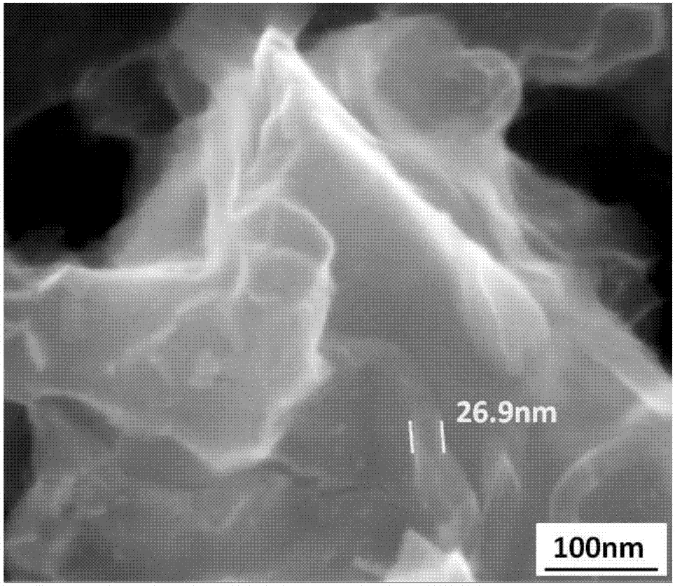
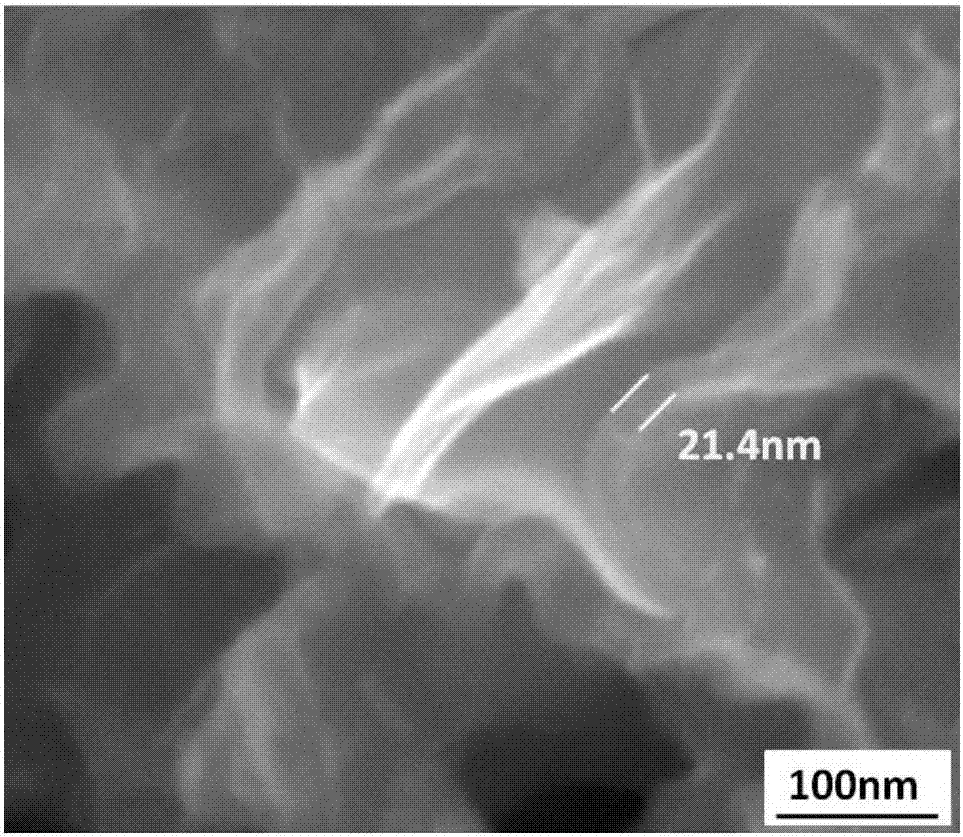
[0025] see figure 1 , 2 . in figure 1 It is a photograph of the cross-section morphology of the low-pressure corroded aluminum foil obtained by D...

Embodiment 3

[0027] Connect the two poles of the power frequency AC power supply to their respective corroded aluminum foils, and immerse them in 5% ammonium acetate solution at 60°C, at 100V, 0.7A / cm 2 , Anodizing under the condition of 55Hz. During the formation process, after the applied voltage increased to 100V, constant voltage anodization was carried out for 20min. Subsequently, the aluminum foil was heat-treated in an air atmosphere at 600° C. for 1 min, and then anodized for 2 min under the same conditions as above. Through the test, compared with the corroded aluminum foil after DC anodization, under the same withstand voltage, the specific capacitance value increases by 2%, the loss value decreases by 3%, and the production efficiency increases by 85%. The obtained anode aluminum foil leakage current parameter K=0.004μA·V -1 ·µF -1 .


PUM

PropertyMeasurementUnit
quality scoreaaaaaaaaaa

Abstract

The invention discloses an industrial-frequency alternating-current anodic oxidation method of an anode aluminum foil for an aluminum electrolytic capacitor and belongs to the technical field of the aluminum electrolytic capacitor. The industrial-frequency alternating-current anodic oxidation method comprises the following steps: firstly respectively connecting the two poles of an industrial-frequency alternating-current power supply with respective etched aluminum foils; subsequently dipping into a formation electrolyte to perform anodic oxidation treatment, and still performing constant-voltage anodic oxidation treatment for 5min to 20min after the impressed voltage is increased to a set voltage; finally thermally treating the aluminum foils which are subjected to the anodic oxidation treatment so as to form an Al2O3 medium film on the surface of each etched aluminum foil. Compared with an etched aluminum foil prepared by means of direct-current anodic oxidation at the same withstand voltage, the etched aluminum foil prepared by the method disclosed by the invention is 1% to 5% higher in specific volume value, 1% to 3% lower in loss value, 0.004-0.008microamp.V<-1>.microfarad<-1> in leakage current parameter K value range, and 30% to 90% higher in production efficiency.

Description

technical field [0001] The invention belongs to the technical field of aluminum electrolytic capacitors, and in particular relates to a power frequency AC anodic oxidation method of anode aluminum foils for aluminum electrolytic capacitors. Background technique [0002] Generally, an aluminum electrolytic capacitor is composed of a corroded and anodized anode aluminum foil, a separator, an electrolyte, and a corroded cathode aluminum foil, wherein the formation of a dielectric film by anodic oxidation is a key step in the preparation of an aluminum electrolytic capacitor. Power frequency alternating current has been studied in the fields of electroplating, electrodeposition, and electrocorrosion. The report of power frequency alternating current in the field of anodic oxidation is currently only available: In 2008, Wang Ximei et al. researched the power frequency anodic oxidation of AZ91D magnesium alloy materials. The research shows that: in the oxidation solution system c...

Claims


Application Information

Patent Timeline
Patent Type & Authority Patents(China)
IPC IPC(8): C25D11/04H01G9/00H01G9/055H01G9/07
CPCC25D11/04H01G9/0032H01G9/055H01G9/07
Inventor 杜显锋林白阁徐友龙
Owner XI AN JIAOTONG UNIV
Learn More