Electronically-controlled adjustable optical attenuator

A technology of dimming attenuation and attenuator, which is applied in optics, instruments, optical components, etc., and can solve the problems affecting the good optical performance and effective controllability of devices, unstable physical/chemical properties, and slow response speed of microfluidic devices etc. to achieve the effect of good maneuverability, easy manufacture and simple structure

Inactive Publication Date: 2016-06-01
NANJING UNIV OF POSTS & TELECOMM
View PDF3 Cites 3 Cited by
  • Summary
  • Abstract
  • Description
  • Claims
  • Application Information

AI Technical Summary

Problems solved by technology

The common disadvantages of these microfluidic optical attenuators based on electrowetting on dielectric (EWOD) are: complex structure, many electrode leads, high voltage required, and slow response time
Moreover, the curved surface of the zoom microlens of EWOD is not spherical in fact, and the shape of the droplet is irregular due to the different contact angles of the front and rear of the micro-droplet driven by electrowetting, which will affect the goodness and effective controllability of the optical performance of the device.
[0005] The invention belongs to the microfluidic optical device, which can well solve the above problems. The attenuation range and return loss are superior to the current general variable optical attenuators. Fast, small insertion loss (0.55dB), large return loss, simple structure, small size, easy to manufacture, cost-integrated, and solve the problem of slow response, complex structure, and insufficient physical / chemical properties in common microfluidic devices. Stability and other issues

Method used


Image

  • Electronically-controlled adjustable optical attenuator
  • Electronically-controlled adjustable optical attenuator
  • Electronically-controlled adjustable optical attenuator

Examples


Embodiment Construction

[0022] The present invention will be described in further detail below in conjunction with the accompanying drawings.

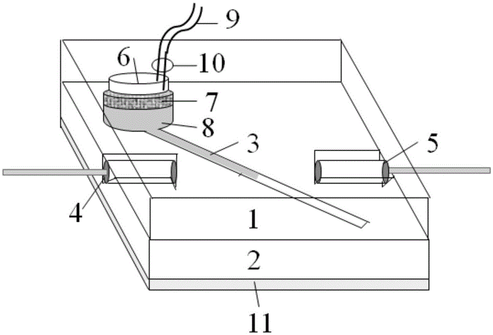
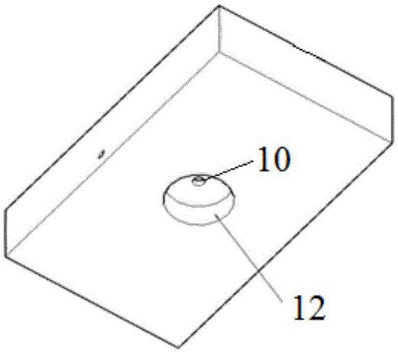
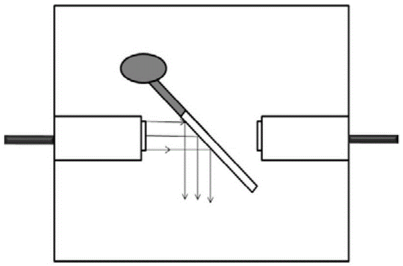
[0023] Such as figure 1 As shown, the present invention provides an electronically controlled adjustable optical attenuator based on microfluidic technology. The adjustable optical attenuator adopts a sandwich structure, the first layer is the cover plate 1, leaving an outlet 10 for the power cord 9, and the inner groove 12 is used to embed the piezoelectric ceramic 6, and the piezoelectric ceramic 6 and the cover plate 1 Bonding; the second layer is a square transparent medium layer 2, including: a micro flow channel 3 on its diagonal, an incident fiber collimator 4, an outgoing fiber collimator 5, piezoelectric ceramics 6, and piezoelectric ceramics The insulating piston sheet 7, the liquid storage tube 8, and the power cord 9 are connected together, wherein the incident and outgoing optical fiber collimators are located in two V-shaped grooves on the same...


PUM


Abstract

The invention discloses an electronically-controlled adjustable optical attenuator. On the basis of the microfluidic technology, a sandwich structure is adopted; the first layer is a cover plate (1), an outlet (10) for a power line (9) is left, and piezoelectric ceramic (6) is embedded in an inner groove (12), and the piezoelectric ceramic (6) is bonded with the cover plate (1); the second layer is a square transparent dielectric layer (2) and comprises a microfluidic channel (3) on the diagonal line, an incident fiber collimator (4), an emergent light fiber collimator (5), the piezoelectric ceramic (6), an insulated piston sheet (7) bonded with the piezoelectric ceramic together, a liquid storage pipe (8) and the power line (9), the upper end of the microfluidic channel (3) is sealed with air by using an elastic thin film, the other end is filled with liquid and communicated with the liquid storage pipe (8), and the liquid refractive index is the same as or similar with that of the square transparent dielectric layer (2); and the third layer is a base (11). The piezoelectric ceramic is controlled to be extended and retracted by voltage, the matching liquid in the microfluidic channel (3) is driven to flow, the position of the matching liquid in the microfluidic channel (3) is controlled, the light intensity coupling efficiency between two fiber collimators is thus mediated, and controllable attenuation adjustment on the light is realized.

Description

technical field [0001] The invention relates to an electronically controlled adjustable optical attenuator based on microfluidic technology, belonging to the technical fields of optical communication and optoelectronic devices. Background technique [0002] Variable Optical Attenuator (Variable Optical Attenuator, VOA for short) is an important optical passive device in the intelligent optical network. Channel gain balance and device protection in wavelength division multiplexing system (referred to as WDM / DWDM). Existing adjustable optical attenuators include mechanical type, waveguide type, liquid crystal type, magneto-optical type, and micromachine (abbreviated as MEMS) type, etc. Among them, the mechanical adjustable optical attenuator is the most mature, but its bulky, complex structure makes it difficult to integrate. In recent years, MEMS dimmable optical attenuators manufactured by micro-mechanical technology have the advantages of small size, light weight, and low...

Claims


Application Information

Patent Timeline
Patent Type & Authority Applications(China)
IPC IPC(8): G02B26/00G02B26/02G02F1/03
CPCG02B26/004G02B26/023G02F1/0327
Inventor 万静薛凤兰吴凌寻府燕君胡健张伟胡芳仁
Owner NANJING UNIV OF POSTS & TELECOMM
Why Eureka
Try Eureka