Cascade refrigerating circulating system coupled with injector

A cycle system and ejector technology, applied in the field of cascade refrigeration cycle systems, can solve the problems of reducing refrigeration capacity, waste, and increasing power consumption of high-temperature stage compressors, so as to improve refrigeration coefficient, improve heat exchange capacity, and improve heat exchange rate. The effect of thermal coefficient

Active Publication Date: 2016-06-08
SOUTHEAST UNIV
View PDF7 Cites 2 Cited by
  • Summary
  • Abstract
  • Description
  • Claims
  • Application Information

AI Technical Summary

Problems solved by technology

Considering the heat transfer temperature difference in the condensing evaporator, the evaporation temperature of the high-temperature stage is about -15°C, so there is a large temperature difference between the evaporator of the high-temperature stage refrigeration cycle and the exhaust gas of the low-temperature stage compressor, which will cause Serious irreversible loss and waste of cooling capacity in the heat exchange process of the evaporator
At the same time, in the high-temperature refrigeration cycle, the liquid refrigerant will also produce flash vapor after throttling. After this part of flash vapor enters the condensing evaporator, not only will it not generate cold energy in the condensing evaporator, but will also occupy the condensing evaporator for heat exchange. The area affects the evaporation of liquid refrigerant, thereby reducing the heat transfer efficiency of the condensing evaporator and reducing the cooling capacity
Not only that, this part of the flash gas that does not produce cooling capacity will be sucked by the high-temperature compressor and compressed to the condensation pressure after passing through the condensing evaporator, which will increase the power consumption of the high-temperature compressor

Method used


Image

  • Cascade refrigerating circulating system coupled with injector
  • Cascade refrigerating circulating system coupled with injector

Examples


Embodiment Construction

[0015] The following combined examples and instructions are attached to the present invention further.

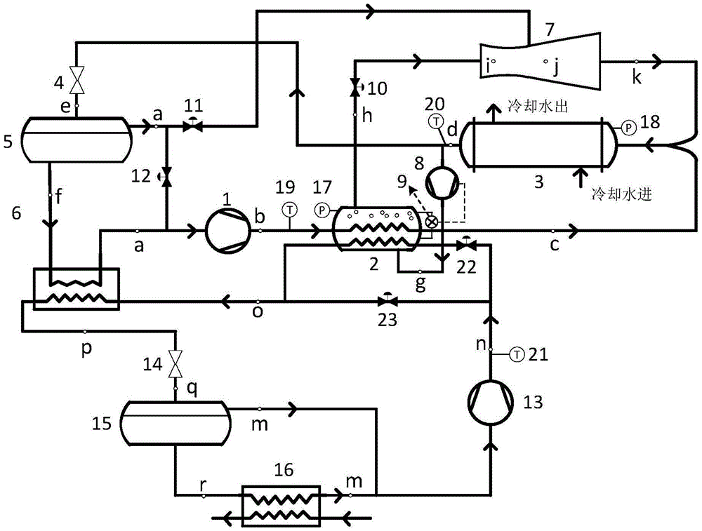
[0016] like figure 1 It is shown that the refrigeration compressor exhaust heat and the spray -to -jet -tojet -coupled of the decorative refrigeration circulation system., Slotal valve, gas liquid separator, evaporator, jet, liquid supercharged pump, liquid level controller, solenoid valve, pressure sensor, temperature sensor, etc.

[0017] Its refrigeration cycle method is:

[0018] The saturated liquid refrigerant after condenser condensation is divided into two roads. After the throwing valve, the throttling valve and cooling down the voltage, and the other road passes through the liquid supercharged pump to enter the three -channel generator.The start -up and stop of the pressure pressure pump is controlled to achieve the purpose of controlling the liquid level of the three -channel generator.

[0019] When the system starts, start the high temperature level first. Due to t...


PUM


Abstract

The invention discloses a cascade refrigerating circulating system coupled with an injector. Overheat steam exhausted by a high-temperature-level compressor and a low-temperature-level compressor in the system will heat and gasify a high-temperature-level overcooled liquid refrigerant which is boosted through a booster pump to be under generation pressure, and generated saturated steam is used as working steam of refrigerant flash evaporation gas which is separated through a gas-liquid separator after injecting of an injector and high-temperature-level throttling are conducted. Due to the fact that sensible heat of overheat gas exhausted by the low-temperature-level compressor is utilized in a three-channel generator, loads of a condensation evaporator are effectively reduced, in other words, the refrigerating amount of high-temperature-level refrigerating circulation is reduced, on the premise of the high-temperature-level and low-temperature-level working conditions and the same low-temperature-level refrigerating amount, refrigerating loads of high-temperature-level circulation and power consumption of the compressors will be reduced, and the COP of the whole cascade refrigerating circulation will be improved. It can be obtained that the refrigerating coefficient of the cascade refrigerating circulating system will be increased by 10% or so compared with the refrigerating coefficient of a traditional cascade refrigerating system through preliminary estimation on the cascade refrigerating system composed of NH3 and CO2.

Description

Technical field [0001] The invention is the field of refrigeration cycle, involving a folded refrigeration circulation system that is coupling with the injection. Background technique [0002] In the traditional folded refrigeration cycle, there is a high -temperature low -temperature compressor exhaust in high heat. After entering the condensed evaporator directly, it must be cooled and then condensed into a saturated liquid or a certain over -cold liquid.The height of cooling and condensation load directly affects the size of high -temperature refrigeration cycle refrigeration.NH 3 And Co 2 For example, the folded refrigeration system composed is an example. When the low-temperature evaporation temperature is -50 ° C and the condensate temperature is -10 ° C, the low-temperature compressor exhausts 2 The temperature is about 60 ° C.Considering the heat exchange temperature difference in the condensed evaporator, the high temperature evaporation temperature is about -15 ° C, s...

Claims


Application Information

Patent Timeline
Patent Type & Authority Applications(China)
IPC IPC(8): F25B7/00F25B25/00F25B41/00F25B41/40
CPCF25B7/00F25B25/005F25B41/00
Inventor 江巍雪杜垲李彦军
Owner SOUTHEAST UNIV
Why Eureka
Try Eureka