Thrombus filter

A filter and thrombus technology, which is applied in the field of medical devices, can solve problems such as too large outer diameter, difficult operation, hard head, etc., and achieve the effects of reducing the risk of device stuck, good adherence, and ensuring blood supply

Active Publication Date: 2016-06-15
VENUS MEDTECH (HANGZHOU) INC
View PDF10 Cites 17 Cited by
  • Summary
  • Abstract
  • Description
  • Claims
  • Application Information

AI Technical Summary

Problems solved by technology

In this scheme, the thrombus interception net is deployed in the aorta, which can intercept the fallen plaque or emboli and protect the downstream branch vessels. The following disadvantages: First, in this scheme, the anti-overflow umbrella is in a closed state in a natural state, and the elasticity of the thrombus interception net is required to expand it in the blood vessel. After catching plaque or emboli, the anti-overflow umbrella relies on its own resilience to recover Closing the opening of the umbrella cover, the closing force is too small, and there is still a risk of plaque or emboli leaking during the process of recovering the thrombus. If the leaked thrombus blocks the vital organs of the patient, it will bring serious consequences; the second , in the narrow blood vessel lumen, because the anti-overflow umbrella is a metal mesh structure, it has a large degree of freedom in the axial direction. During the process of extending and withdrawing the thrombus interception net in the anti-overflow umbrella, there is a problem of anti-overflow Unexpected deformation of the umbrella caused the two to get stuck, making it difficult to retract the overflow-proof umbrella, and it would have to be transferred to surgery for resolution; The wall-attachment of the curved blood vessel is not good. At the same time, the anti-overflow umbrella and the thrombus interception net need a push rod respectively, so the rigidity of the whole device is relatively high, and the relative movement of the two during use is difficult to operate.

Method used


Image

  • Thrombus filter
  • Thrombus filter
  • Thrombus filter

Examples


Embodiment 1

[0038] Embodiment 1, this embodiment is a basic implementation manner.

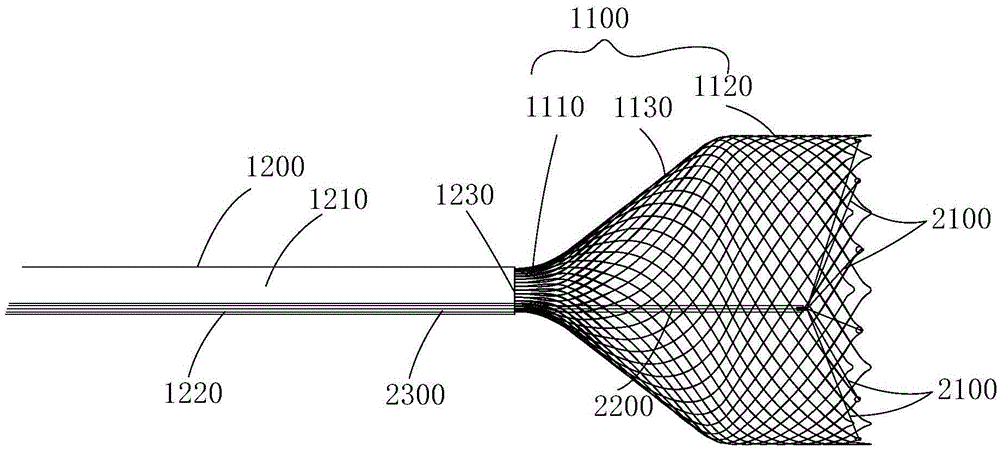
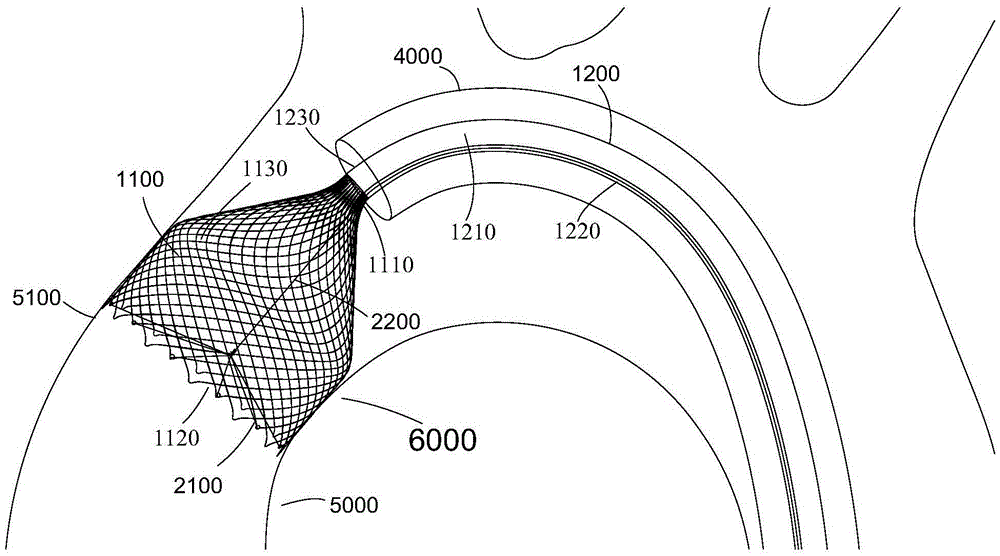
[0039] Such as Figure 1-5 As shown, a thrombus filter includes a handle (not shown in the figure), a filter umbrella 1100 for catching thrombus, a push catheter 1200, and a closing device for shrinking and closing the filter umbrella 1100; the filter umbrella 1100 is Reticulated elastically recoverable funnel-shaped structure, the neck 1110 of the filter umbrella 1100 is fixedly connected with the push conduit 1200, and the push conduit 1200 is provided with an inner cavity along the axial direction, and the cavity surrounded by the filter umbrella 1100 is connected with the push conduit 1200 The inner cavity of the closed space is communicated; the closing device includes a take-up line 2100 for pulling the filter umbrella 1100 into a closed space, and a traction mechanism for pulling the take-up line 2100; the take-up line 2100 is connected to the opening 1120 of the filter umbrella 1100 and Pulling t...

Embodiment 2

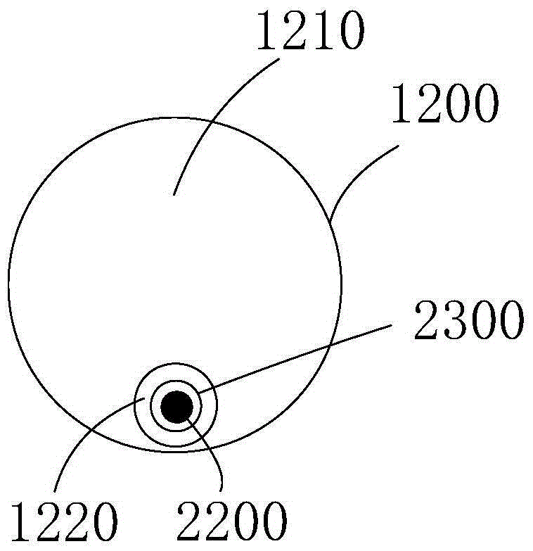
[0060] Example 2, such as Figure 6a , 6b Shown, this embodiment is another kind of implementation. The difference from Embodiment 1 is that the traction mechanism is a traction member 2200 directly worn in the inner cavity of the push catheter 1200. Since the support catheter in Embodiment 1 is cancelled, the traction member 2200 is a tubular or rod-shaped hard material, the end 2210 of the pulling member 2200 is fixedly connected to the take-up wire 2100, and the other end of the pulling member 2200 is fixedly connected to the handle. That is, the thrombus filter 6000 is composed of a filtering umbrella 1100, a pushing catheter 1200, a take-up wire 2100, a traction member 2200 and a handle (not shown), and the pushing action is completed through the traction member 2200, thereby reducing surgical operations. Same as Embodiment 1, the traction member 2200 is located in the side cavity 1220 of the pushing catheter 1200 , and the side cavity 1220 is located at the tube wall o...

Embodiment 3

[0064] Example 3, such as Figure 8 As shown, the intraoperative thrombus filter involved in this embodiment is the same as that in Embodiment 1 by the filter umbrella 1100 , the take-up wire 2100 , the traction member 2200 , the support catheter 2300 and the handle. The difference is that the pushing catheter 1200 in this embodiment is a single-lumen tube. Specifically, it is preferred that the pushing catheter 1200 is provided with an inner lumen passing through both ends of the pushing catheter 1200 along the axial direction, and the outer diameter of the traction mechanism is less than The diameter of the lumen leaves a space for accommodating interventional instruments between the traction mechanism and the lumen; the traction mechanism includes a traction member 2200 and a support catheter 2300 . The lumen of the push catheter 1200 serves as the delivery channel of the interventional instrument and also serves as the delivery channel of the support catheter 2300, which h...


PUM


Abstract

The invention discloses a thrombus filter which comprises a handle, a filter umbrella for capturing thrombi, a push catheter, and a folding device for shrinking and folding the filter umbrella, wherein the filter umbrella adopts a meshy elastically-recoverable funnel-shaped structure; a neck part of the filter umbrella is fixedly connected with the push catheter; an inner cavity is axially formed in the push catheter; a cavity enclosed by the filter umbrella is communicated with the inner cavity of the push catheter; the folding device comprises a take-up unit and a drawing mechanism for drawing the take-up action; the take-up unit is connected with an opening part of the filter umbrella and draws the opening part to be folded, so that the filter umbrella becomes a closed space; the drawing mechanism penetrates the inner cavity of the push catheter, extends towards the opening part of the filter umbrella and is connected with the take-up unit; the push catheter and the drawing mechanism are connected with the handle; the actions of the push catheter and the drawing mechanism are controlled by the handle. The thrombus filter can effectively block exfoliated plaques or emboli, and is simple in structure, small in push resistance and smooth in operation.

Description

technical field [0001] The invention belongs to the technical field of medical devices and relates to a filter, in particular to a thrombus filter used for filtering plaque or thrombus shed during surgery. Background technique [0002] With the wide application of endovascular interventional therapy in the world, its complications are becoming more and more obvious. For example, during balloon dilatation, arterial endarterectomy, vascular atherectomy or stent implantation, blood clots or calcified plaques are broken and detached, and thrombus is generated, which enters the distal end along the direction of blood flow Blood vessels that block the blood supply to vital organs, such as the brain, heart, or other vital organs. This embolism may lead to cerebral infarction, myocardial infarction, pulmonary embolism, etc., and may lead to death in severe cases. Taking interventional aortic valve replacement surgery as an example, due to severe stenosis and calcification of the a...

Claims


Application Information

Patent Timeline
Patent Type & Authority Applications(China)
IPC IPC(8): A61F2/01
CPCA61F2/01A61F2002/016A61F2220/00
Inventor 张庭超王永胜李阳
Owner VENUS MEDTECH (HANGZHOU) INC
Why Eureka
Try Eureka