Circuit structure and manufacturing method thereof

A technology of circuit structure and manufacturing method, which is applied in the direction of circuit, semiconductor/solid-state device manufacturing, electrical components, etc., can solve the problems of delamination between the circuit layer 21 and the passivation layer 22, and yield reduction, so as to improve the delamination phenomenon, The effect of improving product yield

Active Publication Date: 2016-06-29
SILICONWARE PRECISION IND CO LTD
View PDF5 Cites 1 Cited by
  • Summary
  • Abstract
  • Description
  • Claims
  • Application Information

AI Technical Summary

Problems solved by technology

[0013] However, since the material forming the wiring layer 21 is copper, the coefficient of thermal expansion (CTE) between the wiring layer 21 and the passivation layer 22 is different. In the subsequent flip-chip ball planting process, multiple high-temperature processes are required, resulting in Delamination occurs between the circuit layer 21 and the passivation layer 22, resulting in lower yield
[0014] Therefore, how to overcome the above-mentioned problems in the prior art, improve the problem of delamination caused by the difference in thermal expansion coefficient between the circuit layer and the passivation layer, and improve the product yield is an urgent development direction in the industry.

Method used


Image

  • Circuit structure and manufacturing method thereof
  • Circuit structure and manufacturing method thereof
  • Circuit structure and manufacturing method thereof

Examples


no. 1 example

[0060] see Figure 2A and Figure 2D It is a schematic diagram showing the manufacturing method of the circuit structure 3 of the present invention.

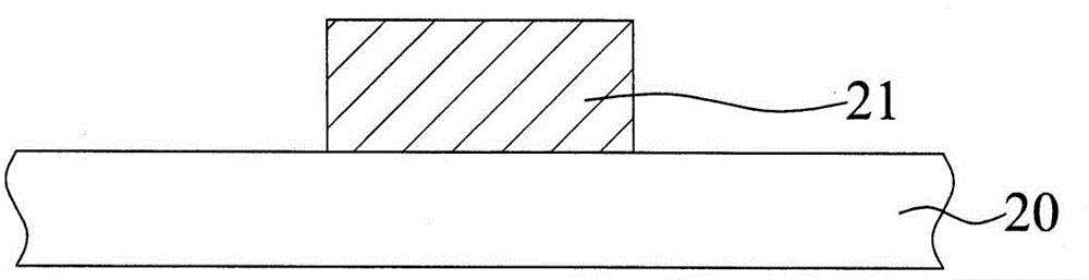
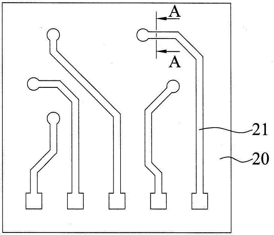
[0061] Such as Figure 2A As shown, a substrate 30 with a circuit layer 31 formed on the surface is provided, and the circuit layer 31 has a first surface 31a and a second surface 31b opposite to each other, and a side surface 31c connecting the first surface 31a and the second surface 31b, wherein , the circuit layer 31 contacts the substrate 30 through the second surface 31b.

[0062] In this embodiment, the substrate 30 is a circuit board, chip, wafer, redistribution structure or silicon interposer. In addition, the substrate may already have at least one circuit layer, and the circuit layer 31 refers to the circuit formed on the outermost layer of the substrate. Furthermore, the material forming the wiring layer 31 is copper.

[0063] Such as Figure 2B As shown, a first dielectric layer 32 is formed on the first surfa...

no. 2 example

[0068] Such as Figure 2D As shown, on the second dielectric layer 33 , a third dielectric layer 34 is formed by chemical vapor deposition, and the reflection index of the third dielectric layer 34 is smaller than the reflection index of the first dielectric layer 32 .

[0069] In this embodiment, the material forming the second dielectric layer is a general deposition rate (approximately ) deposited under silicon oxide, the material forming the third dielectric layer is a general deposition rate (approximately ) Silicon nitride deposited under.

[0070] see Figure 2C , the circuit structure of the present invention includes: a substrate 30; a circuit layer 31 formed on the surface of the substrate 30, the circuit layer 31 has an opposite first surface 31a and a second surface 31b, and connects the first surface 31a and the second surface The side 31c of the surface 31b, wherein the circuit layer 31 contacts the substrate 30 through the second surface 31b; the first diel...

no. 3 example

[0075] see image 3 Compared with the previous embodiment, in the circuit structure 4 of this embodiment, the first dielectric layer 32 is also only formed on the first surface 31a and the side surface 31c of the circuit layer 31, and is not formed on the substrate 30. On the surface, however, the second dielectric layer 33 is not only formed on the first dielectric layer 32, the second dielectric layer 33 also extends to cover the surface of the substrate 30 where the circuit layer 31 is not formed. , that is, the second dielectric layer 33 is formed on the surface of the substrate 30 . In this embodiment, the circuit structure 4 has a third dielectric layer 34 formed on the second dielectric layer 33 .


PUM


Abstract

A circuit structure and a manufacturing method thereof are provided. The circuit structure comprises a substrate, a circuit layer forming on the surface of the substrate and a second dielectric layer forming on a first dielectric layer. The circuit layer comprises a first surface and a second surface which are opposite and side surfaces connecting the first surface and the second surface. The circuit layer is in contact with the substrate via the second surface. A reflective index of the second dielectric layer is smaller than the reflective index of the first dielectric layer. An adhesive force between the second dielectric layer and the circuit layer is enhanced by the first dielectric layer, thereby raising the yield rate of the whole circuit structure.

Description

technical field [0001] The invention relates to a circuit structure, in particular to a circuit structure capable of preventing delamination of a passivation layer on an outer circuit. Background technique [0002] With the vigorous development of the electronics industry, many high-end electronic products are gradually developing towards light, thin, short, small and other high-density directions. With the evolution of packaging technology, chip packaging technology is becoming more and more diversified. Semiconductor packaging The size or volume of the semiconductor package is also continuously reduced, so that the semiconductor package can be thinner and smaller. [0003] Flip-chip technology has the advantages of reducing the chip packaging area and shortening the signal transmission path. It has been widely used in the field of chip packaging, such as Chip Scale Package (CSP), Direct Chip Attached (DCA) and multi-chip die. Multi-Chip Module (MCM) and other types of pac...

Claims


Application Information

Patent Timeline
Patent Type & Authority Applications(China)
IPC IPC(8): H01L23/495H01L21/60
CPCH01L2224/16225H01L2924/15174H01L2924/15311
Inventor 赵俊杰卢俊宏
Owner SILICONWARE PRECISION IND CO LTD
Why Eureka
Try Eureka