Thermal decomposition material, clad material for power system and power system

A technology of power supply system and coating material, applied in the field of energy storage devices, can solve problems such as unreasonable design of power supply system, fire, and inadequate design of collision protection of power supply system, and achieve the effect of avoiding location limitations and monitoring hysteresis

Inactive Publication Date: 2016-07-06
ZHENGZHOU YUTONG BUS CO LTD
View PDF6 Cites 0 Cited by
  • Summary
  • Abstract
  • Description
  • Claims
  • Application Information

AI Technical Summary

Problems solved by technology

[0005] 1) Most of the power systems used for energy vehicles use lithium-ion batteries or super capacitors that use organic electrolytes. Once the organic electrolyte leaks, it is very easy to burn;
[0006] 2) The number of components of the power system is large and difficult to control. For example, Tesla electric vehicles use more than 7,000 18650 cylindrical batteries. Most domestic electric vehicles are equipped with large-capacity lithium-ion batteries, but the number of batteries is also large, which is not easy to achieve Safety control of each battery;
[0007] 3) The voltage of the power supply system is high, generally exceeding 300V, and the safety factor is low;
[0008] 4) The insulation design of the power supply system is unreasonable, which is prone to leakage current, and an arc is formed at the leakage part to cause local heating or fire;
[0009] 5) The thermal management system of the power system cannot monitor the temperature change of each single battery well, and cannot monitor the local thermal runaway inside the power system;
[0010] 6) The collision protection design of the power system is not in place. After the battery is seriously deformed due to the collision of the whole vehicle, it is easy to cause a short circuit of the battery and cause thermal runaway;
[0011] 7) The design of the high-voltage wire harness and low-voltage wire harness of the power system is unreasonable, resulting in a short circuit of the high-voltage wire harness or low-voltage wire harness, local heating or fire;
The gas detection and alarm circuit detects the gas generated by the battery itself. The concentration of the gas is related to the reaction inside the battery and has nothing to do with the temperature of the battery, so it cannot monitor the local thermal runaway of the battery.

Method used


Image

  • Thermal decomposition material, clad material for power system and power system
  • Thermal decomposition material, clad material for power system and power system
  • Thermal decomposition material, clad material for power system and power system

Examples


Embodiment 1

[0054] The pyrolysis material of the present embodiment is made up of the component of following percentage by weight: 10% inorganic foaming agent sodium bicarbonate (NaHCO 3 ), 60% of the organic blowing agent azodicarbonamide (AC), 20% of the organic blowing agent diphenylsulfonyl hydrazide oxide (OT), and 10% of the additive zinc oxide (ZnO). The pyrolysis material in this example can decompose and release decomposition gas at 100°C±5°C, and the main component of the decomposition gas released by the pyrolysis material within this temperature range is CO 2 , N 2 Wait for gas.

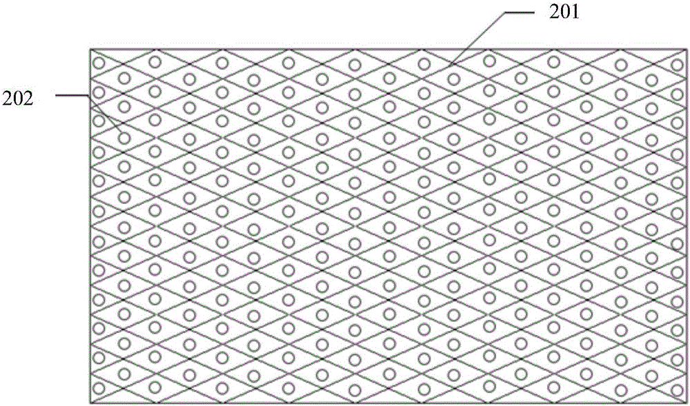
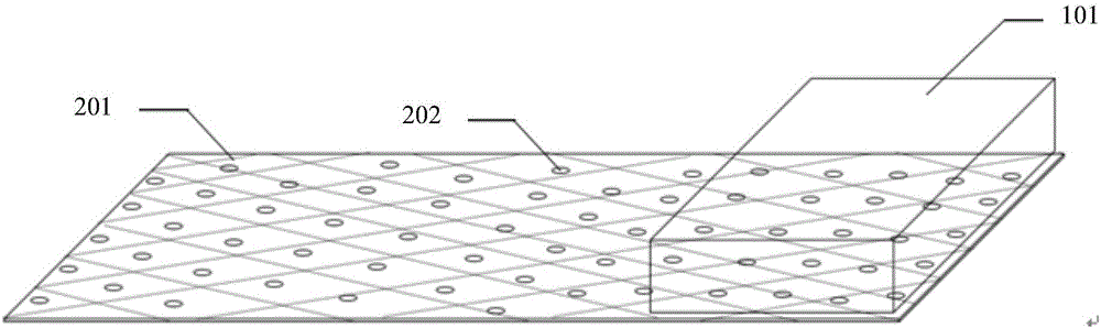
[0055] The cladding material for the power supply system of this embodiment includes a base material 201 and the above-mentioned thermal decomposition material 202 attached to the base material (such as figure 2 shown), the base material is PP. The method of attachment is as follows: use a porous substrate with a large number of pore structures on the surface and inside of the substrate, mix the ...

Embodiment 2

[0057] The pyrolysis material of the present embodiment is made up of the component of following percentage by weight: 80% inorganic blowing agent sodium bicarbonate (NaHCO 3 ), 10% of the organic blowing agent azodicarbonamide (AC), 5% of the organic blowing agent diphenylsulfonyl hydrazide oxide (OT), and 5% of the auxiliary agent zinc oxide (ZnO). The pyrolysis material in this example can decompose and release decomposition gas at 130°C±5°C, and the main component of the decomposition gas released by the pyrolysis material within this temperature range is CO 2 , N 2 Wait for gas.

[0058] The covering material for a power supply system in this embodiment includes a base material and the above-mentioned pyrolysis material attached to the base material, and the base material is PP. The method of attachment is as follows: use a porous substrate with a large number of pore structures on the surface and inside of the substrate, mix the above-mentioned pyrolysis materials even...

Embodiment 3

[0060] The pyrolysis material of the present embodiment is made up of the component of following percentage by weight: 5% inorganic foaming agent sodium bicarbonate (NaHCO 3 ), 10% of the organic foaming agent azodicarbonamide (AC), 55% of the organic foaming agent diphenylsulfonyl hydrazide oxide (OT), and 30% of the additive zinc oxide (ZnO). The pyrolysis material in this embodiment can decompose and release decomposition gas at 140°C±5°C, and the main component of the decomposition gas released by the pyrolysis material within this temperature range is CO 2 , N 2 Wait for gas.

[0061] The covering material for a power supply system in this embodiment includes a base material and the above-mentioned pyrolysis material attached to the base material, and the base material is PP. The method of attachment is as follows: use a porous substrate with a large number of pore structures on the surface and inside of the substrate, mix the above-mentioned pyrolysis materials evenly,...


PUM

PropertyMeasurementUnit
thicknessaaaaaaaaaa
thicknessaaaaaaaaaa
thicknessaaaaaaaaaa

Abstract

The invention relates to a thermal decomposition material, a clad material for a power system and the power system, and belongs to the technical field of energy storage devices.The thermal decomposition material is prepared from, by weight, 0-100% of an inorganic foaming agent, 0-100% of an organic foaming agent and 0-30% of auxiliaries.The inorganic foaming agent is one or more of sodium bicarbonate, sodium carbonate, ammonium bicardonate and ammonium carbonate.The organic foaming agent is azodicarbonamide and or hydrazides compounds.According to the thermal decomposition material, the inorganic foaming agent and the organic foaming agent are blended according to different proportions, specific decomposed gas can be released at the certain temperature, and the thermal decomposition material is arranged inside a box of the power system; when the local temperature of the power system is increased to a set value, the thermal decomposition material will release corresponding gas, and the temperature changing conditions inside the power system can be known only by monitoring the concentration of the gas.

Description

technical field [0001] The invention relates to a thermal decomposition material, a coating material for a power supply system and a power supply system, and belongs to the technical field of energy storage devices. Background technique [0002] According to statistics from relevant agencies, the sales volume of new energy vehicles in my country is expected to reach 220,000 to 250,000 in 2015. From January to October 2015, the cumulative production of new energy vehicles in my country was 181,225, and the cumulative sales were 171,145, a year-on-year increase of 2.7. Among them, the cumulative production and sales of pure electric vehicles were 121,099 and 113,810, a year-on-year increase of 3.3 and 3.9 times; the cumulative production and sales of plug-in hybrid vehicles were 60,126 and 57,335, a year-on-year increase of 1.9 times And 1.8 times, the electric vehicle industry has shown a good momentum of development. [0003] With the expansion of the industrial scale of elec...

Claims


Application Information

Patent Timeline
Patent Type & Authority Applications(China)
IPC IPC(8): C09D7/00C08J9/36G01R31/40
CPCC09D7/00C08J9/365C08J2323/12G01R31/40
Inventor 曹瑞中周时国
Owner ZHENGZHOU YUTONG BUS CO LTD
Why Eureka
Try Eureka