Method for producing liquid crystal display

A liquid crystal display, black matrix technology, applied in instruments, nonlinear optics, optics, etc., to achieve the effects of high contrast, high portability, and increased color confusion

Inactive Publication Date: 2016-07-27
TUNGHSU KUNSHAN DISPLAY MATERIAL CO LTD +2
View PDF5 Cites 2 Cited by
  • Summary
  • Abstract
  • Description
  • Claims
  • Application Information

AI Technical Summary

Problems solved by technology

[0006] However, with the increasing requirements of customers for the clarity and perception of liquid crystal displays, it is imminent to st

Method used


Image

  • Method for producing liquid crystal display
  • Method for producing liquid crystal display
  • Method for producing liquid crystal display

Examples


Example Embodiment

[0073] In the present invention, the preparation method of the color filter can be a conventional method in the field, for example, it can include: first, cleaning the glass substrate, then coating the BM photoresist, exposing and developing the BM to form a first black matrix; The photoresist was coated with a resin composition containing color pigments (C.I. Pigment Red 254 / C.I. Pigment Yellow 139=80 / 20), and then masked and UV exposed and developed to form a red base film on the substrate. The color pigment (C.I. Pigment Green 36 / C.I. Pigment Yellow 150=60 / 40) resin composition forms a green base film on the substrate; then the resin composition containing the color pigment (C.I. Pigment Blue 15:6) is coated on the substrate by a similar method. The blue base film is formed thereon, wherein the order of forming the red base film, the green base film and the blue base film is not necessarily carried out in the above-mentioned order.

[0074] In addition, the materials of the...

Example Embodiment

[0077] Example

[0078] Silicon-based microparticles are silicon-based microparticles produced by Ube Nitto Company, Japan, and are made of aluminum silicate with alumina and silicon dioxide as the main components, and are purchased from Ube Nitto Company.

Example Embodiment

[0079] Preparation example

[0080] Prepare red base film, green base film and blue base film according to the formula in Table 1 below. The specific preparation method of color filter is as follows: first, the glass substrate is cleaned, then BM photoresist coating, exposure and development of BM to form The first black matrix (the material of the first black matrix is ​​similar to the material in the red base film, the first black matrix does not contain microparticles with light diffusion function, and the red pigment in the red base film is replaced with the same amount of carbon black) Then photoresist is coated with a resin composition containing color pigments (C.I. Pigment Red 254 / C.I. Pigment Yellow 139=80 / 20) on it, and then photomask and UV exposure and development are used to form a red base film on the substrate, using A resin composition containing a color pigment (C.I. Pigment Green 36 / C.I. Pigment Yellow 150=60 / 40) was formed on a substrate in a similar manner ...


PUM

PropertyMeasurementUnit
Widthaaaaaaaaaa
Heightaaaaaaaaaa
Widthaaaaaaaaaa

Abstract

The invention relates to the field of liquid crystal display, and discloses a method for producing a liquid crystal display, comprising: configuring the liquid crystal display to include: a color filter, a columnar spacer and a second black matrix, the color filter includes a color layer, located The first black matrix between the color base films of the color layer and the protective layer covering the color layer, the second black matrix is ​​located on the opposite side of the first black matrix, and the columnar spacers are located between the protective layer and the second black matrix, The color layer includes a red base film layer, a green base film layer and a blue base film layer arranged horizontally in sequence, and the color layer contains microparticles with a light diffusion function; the width of the second black matrix is ​​configured to be greater than the width of the first black matrix , and determine the second black matrix width according to various known parameters. The liquid crystal display produced by the method of the invention has high contrast ratio, high-quality picture display and high portability.

Description

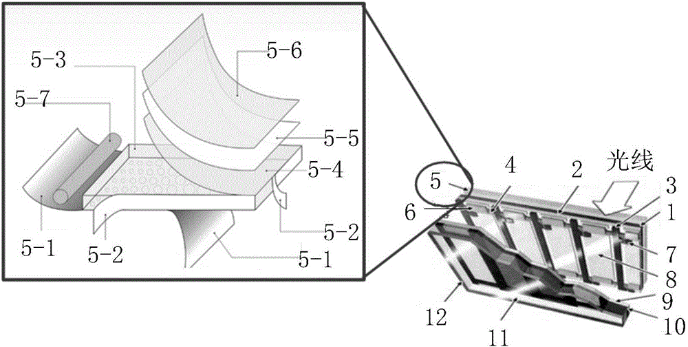
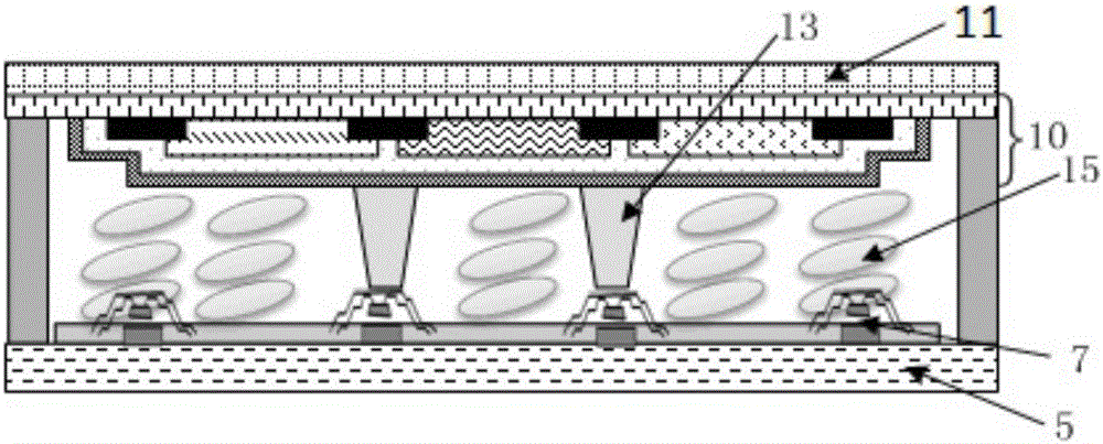
technical field [0001] The present invention relates to the field of liquid crystal display, in particular, to a method for producing a liquid crystal display. Background technique [0002] figure 1 The structure of a conventional liquid crystal display and a schematic diagram of an enlarged backlight module are shown. A traditional liquid crystal display includes a lower polarizing glass 1, a lower glass substrate 2, column data lines 3, row data lines 4, backlight modules 5, storage capacitors 6, thin film transistor arrays 7, transparent display electrodes 8, transparent common electrodes 9, color The filter 10, the upper glass substrate 11, the upper polarizing glass 12, and the like. [0003] figure 2 A cross-sectional view of a conventional liquid crystal display is shown, and it can be seen from the cross-sectional view that, in addition to the backlight module 5, the thin film transistor array 7, and the color filter 10, the conventional liquid crystal display al...

Claims


Application Information

Patent Timeline
IPC IPC(8): G02F1/1335
CPCG02F1/133512G02F1/133504
Inventor 萧毅豪
Owner TUNGHSU KUNSHAN DISPLAY MATERIAL CO LTD
Why Eureka
Try Eureka