Gasification supercritical CO2 cycle power generation system

A cycle power generation and supercritical technology, which is applied in gasification process, machine/engine, and combustible gas production, can solve the problems of low steam flow rate, small turbine inlet and outlet temperature ratio, and difficult efficiency, so as to reduce oxygen consumption and The effect of air separation power consumption, increasing the total heat transfer on the hot side, and increasing the flow rate of the working fluid on the hot side

Active Publication Date: 2016-08-03
INST OF ENGINEERING THERMOPHYSICS - CHINESE ACAD OF SCI
View PDF5 Cites 19 Cited by
  • Summary
  • Abstract
  • Description
  • Claims
  • Application Information

AI Technical Summary

Problems solved by technology

However, due to the supercritical CO 2 The physical properties of the working fluid, the above two types of cycles face two problems: 1) CO under high pressure 2 As the temperature decreases, the specific heat will first increase and then decrease, which is prone to the problem of heat transfer mismatch in the low temperature section, which will bring about a large loss; 2) Under the operating parameters of the turbine, CO 2 The specific heat ratio is lower than that of air or water vapor. At the same drop pressure ratio, the temperature ratio of the inlet and outlet of the turbine is small, and the exhaust gas temperature of the turbine is high. Due to the limitation of the material of the regenerator, the inlet temperature of the turbine cannot be increased, and it is difficult to improve the efficiency.
Due to the steam cycle and CO 2 Due to the difference in circulating working medium, it is impossible to share the equipment, so it is necessary to set up two independent power ge

Method used


Image

  • Gasification supercritical CO2 cycle power generation system
  • Gasification supercritical CO2 cycle power generation system
  • Gasification supercritical CO2 cycle power generation system

Examples


Embodiment Construction

[0031] In order to make the object, technical solution and advantages of the present invention clearer, the present invention will be further described in detail below with reference to the accompanying drawings and examples. The following description of the embodiments of the present invention with reference to the accompanying drawings is intended to explain the general inventive concept of the present invention, but should not be construed as a limitation of the present invention.

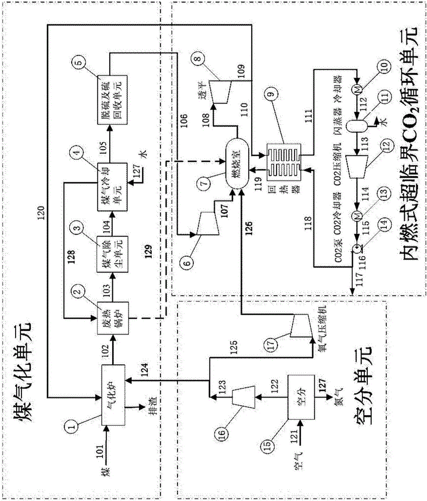
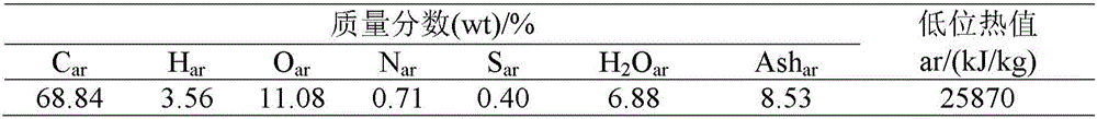
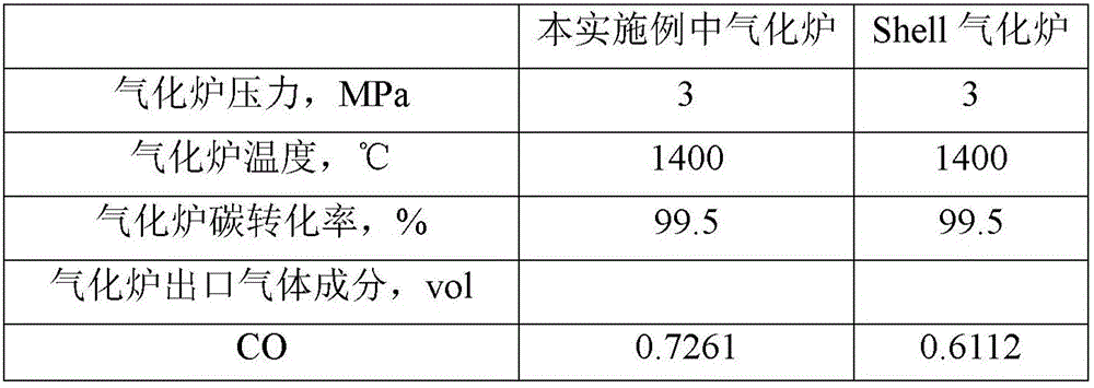
[0032] see figure 1 , a coal gasification supercritical CO proposed by the present invention 2 Circulation power generation system, coal 101 enters gasifier 1 at high temperature rich in CO 2 Under the action of working fluid 120 and oxygen 124, the reaction generates high-temperature crude synthesis gas 102, which is cooled to about 350°C by waste heat boiler 2 to become medium-temperature crude synthesis gas 103, and then enters dust removal unit 3 to remove most of the solid impurities. Th...


PUM


Abstract

A gasification supercritical CO2 cycle power generation system comprises a gasification unit, an air distribution unit and an internal combustion type supercritical CO2 circulation unit, wherein air is input into the air distribution unit, oxygen is generated and output in two paths, one path of oxygen is input into a gasification furnace, and the other path of oxygen is input into a combustion chamber of the internal combustion type supercritical CO2 circulation unit .The internal combustion type supercritical CO2 circulation unit further comprises a turbine for converting heat energy into mechanical energy and a heat regeneration unit used for heat exchanging, and a part of gas is extracted from the portion between turbine stages, or a turbine outlet or a cold side hot end outlet of the heat regeneration unit to serve as a gasification agent to be input into the gasification furnace in the gasification unit .While zero CO2 emission of the gasification supercritical CO2 cycle power generation system is achieved, high system efficiency is obtained, and the net efficiency is higher than that of an integrated gasification combined cycle power generation system based on pre-combustion trapping by 8-14%.

Description

technical field [0001] The invention belongs to the field of energy power and coal chemical industry, in particular to a coal gasification supercritical CO 2 cycle power generation system. Background technique [0002] Under my country's coal-based energy structure, how to reduce CO2 in coal-based power stations efficiently and at low cost 2 Emissions are an important issue facing the energy sector. Conventional coal-based power station CO 2 The technical routes for emission reduction include pre-combustion capture, post-combustion capture, and oxygen-enriched combustion. [0003] Post-combustion capture refers to the separation and capture of CO from flue gas after combustion 2 , the main application object is the conventional pulverized coal power station. Its main advantages are mature technology, simple principle and good inheritance to existing power stations. The disadvantage is that due to the large volume flow of flue gas after combustion, CO 2 The partial pre...

Claims


Application Information

Patent Timeline
IPC IPC(8): C10J3/00F02C6/00F02C3/22F02C3/30F02C6/18F02C6/04
CPCC10J3/00C10J2300/093C10J2300/0953F02C3/22F02C3/30F02C6/00F02C6/04F02C6/18Y02E20/16Y02E20/18Y02P20/54
Inventor 迟金玲张士杰肖云汉
Owner INST OF ENGINEERING THERMOPHYSICS - CHINESE ACAD OF SCI
Why Eureka
Try Eureka