Processing method of carbon fiber weaving fabric

A treatment method and carbon fiber technology, applied in fiber treatment, carbon fiber, physical treatment and other directions, can solve the problems of carbon fiber damage, inability to use carbon fiber fabric surface treatment, affecting the preparation of carbon fiber composite materials, etc., to achieve good microwave absorption performance, eliminate carbon fiber effects of damage

Active Publication Date: 2016-08-10
PLA UNIV OF SCI & TECH
View PDF3 Cites 2 Cited by
  • Summary
  • Abstract
  • Description
  • Claims
  • Application Information

AI Technical Summary

Problems solved by technology

The design of this screen makes it effective for ASPN to reduce the uneven discharge of steel alloy surface treatment. However, carbon fibers placed under the bell-type screen will still produce discharge filaments, resulting in damage to carbon fibers. Therefore, it cannot be used for surface treatment of carbon fiber woven fabrics.
[0006] It has been reported in open literature that the surface treatment of carbon fiber woven fabrics is carried out by plasma-enhanced vapor deposition (PECVD equipment) using low-temperature ammonia plasma method (Zhu Naishu, Effects of plasma treatment and curing methods on the dynamic mechanical properties of carbon fiber composite materials, China Surface Engineering, 2010,23(5)), which can meet the requirement of firm bonding between carbon fiber woven cloth and resin matrix. The storage modulus of the glassy state of the prepared carbon fiber composite material can reach 10.9Gpa, and the measured modulus of the untreated material is 8Gpa. However, It can only improve the bonding strength between the carbon fiber surface and the resin, but cannot change the microwave absorption performance of the carbon fiber woven fabric at the same time, thus affecting the preparation of carbon fiber composite materials used for microwave rapid repair of engineering equipment

Method used


Image

  • Processing method of carbon fiber weaving fabric
  • Processing method of carbon fiber weaving fabric

Examples


Embodiment 1

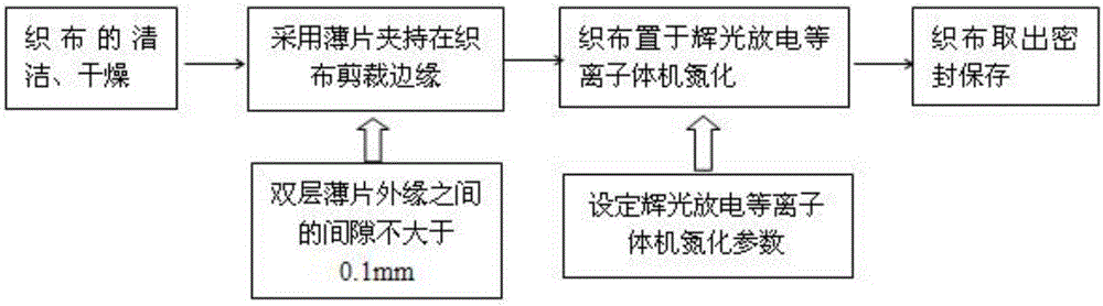
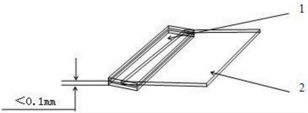
[0025] After the carbon fiber woven cloth is cleaned and dried, it is clamped on the cutting edge surface of the carbon fiber woven cloth with double-layer alloy steel sheets, and the gap between the outer edges of the double-layer sheets is not greater than 0.1mm. Arrange the clamped carbon fiber fabric into the glow plasma treatment machine and place it on the cathode workbench of the glow plasma treatment machine. Low-temperature and low-pressure nitrogen ion treatment is carried out at a temperature of 100° C., a treatment time of 120 minutes, and a treatment pressure of 200 Pa. The treated carbon fiber fabric is obtained.

[0026] A section of carbon fiber bundle in the carbon fiber woven cloth was taken to measure the resistivity value of 2.96Ω·cm, and the resistivity of untreated carbon fiber was 1.93Ω·cm. The influence of this change on the mechanical properties of the material was further analyzed. The carbon fiber plate is tested on a dynamic thermomechanical analyz...

Embodiment 2

[0028] After the carbon fiber woven cloth is cleaned and dried, it is clamped on the cutting edge surface of the carbon fiber woven cloth with double-layer diamond sheets, and the gap between the outer edges of the double-layer sheets is not greater than 0.1mm. Arrange the clamped carbon fiber fabric into the glow plasma treatment machine and place it on the cathode workbench of the glow plasma treatment machine. Low-temperature and low-pressure nitrogen ion treatment is carried out at a temperature of 300° C., a treatment time of 80 minutes, and a treatment pressure of 120 Pa. The treated carbon fiber fabric is obtained.

[0029] A section of carbon fiber bundle in the carbon fiber woven cloth was taken to measure the resistivity value of 3.74Ω·cm, and the influence of this change on the mechanical properties of the material was further analyzed. The carbon fiber plate is tested on a dynamic thermomechanical analyzer. The normal temperature glassy storage modulus of the carb...

Embodiment 3

[0031] After the carbon fiber woven cloth is cleaned and dried, it is clamped on the cutting edge surface of the carbon fiber woven cloth with double-layer diamond-like sheets, and the gap between the outer edges of the double-layer sheets is not greater than 0.1mm. Arrange the clamped carbon fiber fabric into the glow plasma treatment machine and place it on the cathode workbench of the glow plasma treatment machine. Low-temperature and low-pressure nitrogen ion treatment is carried out at a temperature of 500° C., a treatment time of 30 minutes, and a treatment pressure of 50 Pa. The treated carbon fiber fabric is obtained.

[0032] A section of carbon fiber bundle in the carbon fiber woven cloth was taken to measure the resistivity value of 3.48Ω·cm, and the influence of this change on the mechanical properties of the material was further analyzed. The carbon fiber plate is tested on a dynamic thermomechanical analyzer. The normal temperature glassy storage modulus of the ...


PUM

PropertyMeasurementUnit
Resistivity valueaaaaaaaaaa
Resistivityaaaaaaaaaa
Modulusaaaaaaaaaa

Abstract

The invention discloses a processing method of carbon fiber weaving fabric. The method comprises the following steps of (10) weaving fabric clamping: clamping the two sides of the shearing edges of the cleaned and dried fabric weaving fabric by a double-layer rigid thin sheet; (20) surface nitriding: putting the clamped carbon fiber weaving fabric into a glow plasma processing machine, and performing low-temperature and low-pressure nitrogen ion processing to obtain the processed carbon fiber weaving fabric. The carbon fiber weaving fabric treated by the method has the advantages that the bonding with a resin base body is firm; meanwhile, good microwave absorption performance is realized.

Description

technical field [0001] The invention belongs to the technical field of carbon fiber composite material preparation, in particular to a carbon fiber weaving treatment method with good microwave absorption performance and firm bonding with a resin matrix. Background technique [0002] Various equipment (such as aircraft, vehicles, and ships) will be damaged by cracks, gaps, etc. under the circumstances of impact or bullet damage, which seriously threatens the safety of equipment use. The use of fiber composite materials to bond and repair damaged parts is widely used and effective in emergency repairs. However, during the use of composite materials, it is usually necessary to apply external heat energy to cure them. For example, heating with electric blankets takes a long time for curing and molding, and the implementation conditions are difficult to meet the needs of rapid repairs. In the 1990s, the invention of portable microwave radiators enabled high-power microwave extra...

Claims


Application Information

Patent Timeline
IPC IPC(8): D06M10/00D06M101/40
CPCD06M10/00D06M2101/40
Inventor 朱乃姝马世宁夏志成邬建华孔新立王源孙晓峰戴银所李红英
Owner PLA UNIV OF SCI & TECH
Why Eureka
Try Eureka