
Filter circuit of high-voltage drive circuit and high-voltage drive circuit

A high-voltage drive circuit and filter circuit technology, which is applied in logic circuits, electrical components, and electric pulse generation, can solve the problems of fast turn-on speed, driving influence, and slow turn-off speed, and achieve accurate differential mode noise filtering ability, Improves noise filtering efficiency and prevents noise interference

Active Publication Date: 2016-08-10
SHENZHEN XINER SEMICON TECH CO LTD
View PDF4 Cites 9 Cited by
  • Summary
  • Abstract
  • Description
  • Claims
  • Application Information

AI Technical Summary

Problems solved by technology

In the level shift circuit, the turn-off speed of NMOS transistor N1 and NMOS transistor N2 is relatively slow, and the turn-on speed is relatively fast, so that the response time difference between different flipping threshold inverter circuits is small, so that only a small or even no output voltage can be generated. Differential mode filter time
It is understandable that if the NMOS transistor N1 and NMOS transistor N2 cannot filter out the differential mode noise when they are turned on quickly, it will affect the driving of the MOSFET or IGBT by the high voltage drive circuit

Method used


Image

  • Filter circuit of high-voltage drive circuit and high-voltage drive circuit
  • Filter circuit of high-voltage drive circuit and high-voltage drive circuit
  • Filter circuit of high-voltage drive circuit and high-voltage drive circuit

Examples


Embodiment Construction

[0042] In order to have a clearer understanding of the technical features, purposes and effects of the present invention, the specific implementation manners of the present invention will now be described in detail with reference to the accompanying drawings.

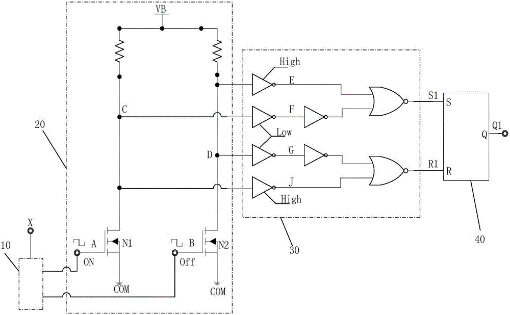
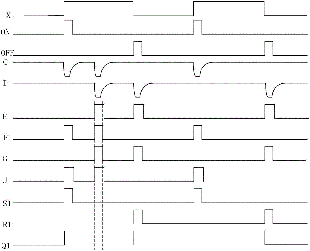
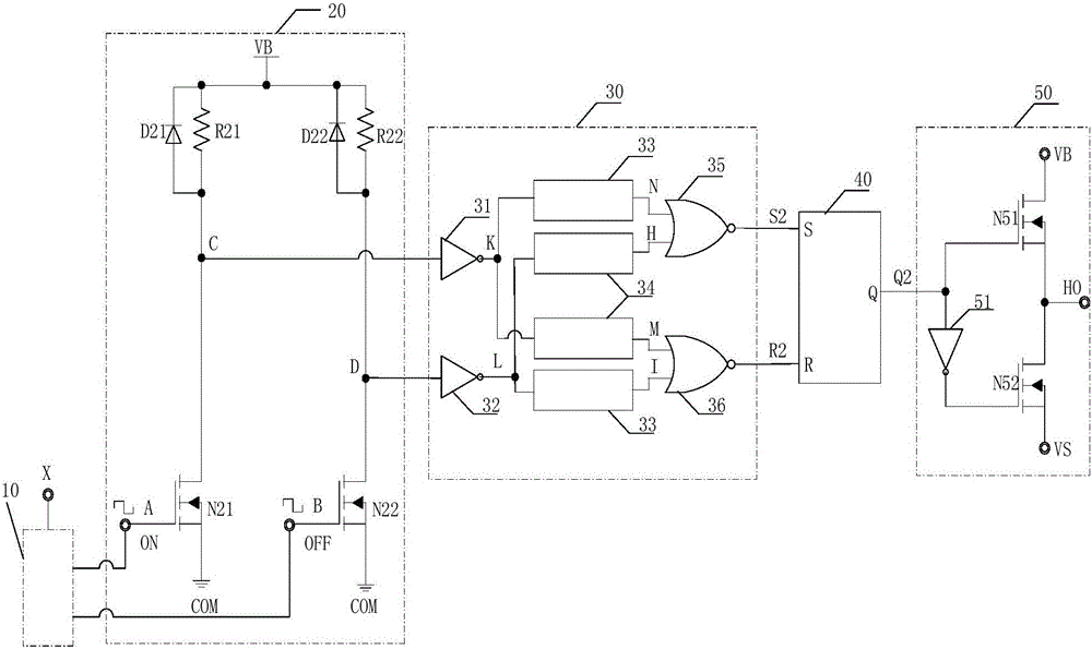
[0043] image 3 and Figure 4 A schematic diagram and a signal logic diagram of the high-voltage drive circuit in this embodiment are shown respectively. The high voltage driving circuit includes a narrow pulse signal generating circuit 10 , a level shifting circuit 20 , a filter circuit 30 , an RS flip-flop 40 and a current amplifying circuit 50 .

[0044] The input end of the narrow pulse signal generation circuit 10 is used to receive the original pulse signal X of 0-15V, and the rising edge narrow pulse signal ON and the falling edge narrow pulse signal are generated respectively on the rising edge and falling edge of the original pulse signal X of 0-15V OFF, and output a narrow pulse signal ON with a rising edge ...


PUM


Abstract

The invention discloses a filter circuit of a high-voltage drive circuit and a high-voltage drive circuit. The filter circuit comprises a first inverter, a second inverter, a first delayed filter circuit, a second delayed filter circuit, a first NOR gate, and a second NOR gate. The first inverter receives a first level shifting signal and outputs a first inverting signal; the second inverter receives a second level shifting signal and outputs a second inverting signal; the first delayed filter circuit receives the first inverting signal and the second inverting signal respectively and outputs a first short time-delay signal and a second short time-delay signal; and the second delayed filter circuit receives the second inverting signal and the first inverting signal respectively and outputs a first long time-delay signal and a second long time-delay signal. The first NOR gate receives the first short time-delay signal and the first long time-delay signal and outputs a first NOR signal; and the second NOR gate receives the second short time-delay signal and the second long time-delay signal and outputs a second NOR signal. According to the filter circuit, the capability of filtering differential mode noises is enhanced while the common-mode noises are filtered and the noise filter efficiency is improved.

Description

technical field [0001] The invention relates to the field of high-voltage integrated circuits, in particular to digital-analog hybrid filter technology in high-voltage integrated circuits, and in particular to a filter circuit and a high-voltage drive circuit of a high-voltage drive circuit. Background technique [0002] High-voltage integrated circuit (HVIC) is a gate drive circuit with functions such as various protection circuits, low-voltage control circuits, and high-voltage power devices. It combines power electronics with semiconductor technology and significantly improves the integration and stability of the whole machine. , has the advantages of high integration density, small size, fast speed, and low power consumption. It gradually replaces traditional discrete devices and is increasingly used in MOSFETs (Metal-Oxide-Semiconductor or Field-Effect Transistor, metal-oxide layer -Semiconductor-field effect transistor), IGBT (Insulated Gate Bipolar Transistor, insulat...

Claims


Application Information

Patent Timeline
Patent Type & Authority Applications(China)
IPC IPC(8): H03K19/0944H03K5/1252H03K3/013
CPCH03K3/013H03K5/1252H03K19/0944
Inventor 刘圭高存旗刘杰
Owner SHENZHEN XINER SEMICON TECH CO LTD
Learn More