A method of falling film melt polycondensation reaction between rows of tubes for preparing high-viscosity melt and its reactor

A technology of melt polycondensation and reactor, which is applied in the field of falling film melt polycondensation reaction between rows of tubes for preparing high-viscosity melt and its reactor, which can solve the problem of increased film-forming area and surface renewal frequency and difficulties in the application of high-viscosity materials , complex built-in structure and other problems, to achieve the effect of simple and feasible reaction method, uniform and controllable residence time, and large flow film forming area

Active Publication Date: 2018-06-12
ZHEJIANG SCI-TECH UNIV
View PDF4 Cites 0 Cited by
  • Summary
  • Abstract
  • Description
  • Claims
  • Application Information

AI Technical Summary

Problems solved by technology

The tube-plate tower reactor mainly relies on the design of internal components to make the molten material form a film on the surface structure of the tube or plate. Compared with the traditional horizontal stirring polycondensation reactor, its film-forming area and surface renewal frequency are higher, but its The built-in structure is complex, and it is easy to generate stagnation areas, resulting in melt degradation, and it is difficult to produce high-viscosity materials.
The falling film reactor outside the tube can make the material flow down in the form of a film along the outer surface of the tube. Since the material flows down naturally by gravity, there will be no clogging problem. This type of reactor has a relatively simple structure, a large mass transfer interface and a Uniform temperature and other advantages, but because the liquid film of the wall-attached free falling film flow presents a semi-parabolic velocity distribution from the inside to the outside, the surface velocity of the melt film is much higher than that of the area near the wall, and the residence time of the outer film is too short and the inside The film residence time is too long

Method used


Image

  • A method of falling film melt polycondensation reaction between rows of tubes for preparing high-viscosity melt and its reactor
  • A method of falling film melt polycondensation reaction between rows of tubes for preparing high-viscosity melt and its reactor
  • A method of falling film melt polycondensation reaction between rows of tubes for preparing high-viscosity melt and its reactor

Examples


Embodiment 1

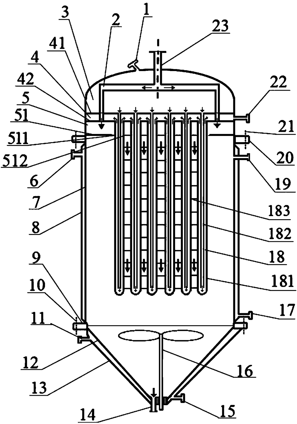
[0029] Embodiment 1, with reference to attached figure 1 , 4 , 5a, 5b, 5c.

[0030] In this embodiment, the outer tube 181 of the falling film support tube 18 is a straight tube with a constant diameter.

[0031] A falling film melt polycondensation reactor between rows of tubes for preparing a high-viscosity melt provided by this embodiment, such as figure 1 As shown, it includes a vertical housing 7, a material feed box connected to the upper end of the vertical housing 7 and a bottom shell 12 at the lower end, a heat medium outflow box 4 is arranged above the material feed box 5, and the heat medium flows out A heat medium inflow box 3 is provided on the box 4, a reactor heat medium inlet 1 is arranged on the heat medium inflow box 3, and a reactor heat medium outlet 22 is arranged on the heat medium outflow box 4, arranged in rows The falling film support pipe 18 is connected to the heat medium outflow box 4 and the heat medium inflow box 3 to form a heat medium circulati...

Embodiment 2

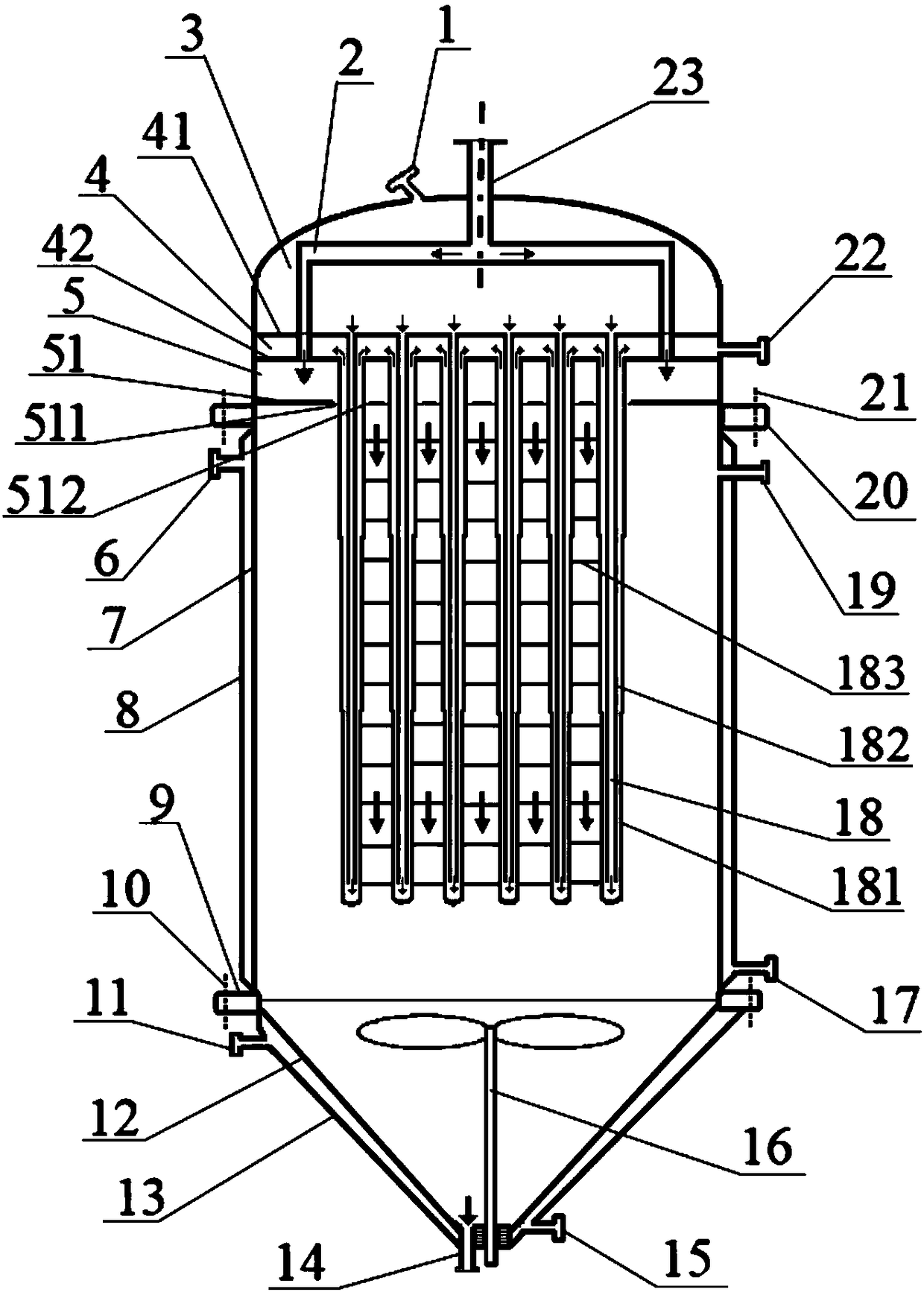
[0051] Embodiment 2, with reference to attached figure 2 , 4 , 5a, 5b, 5c.

[0052] In this embodiment, the outer tube 181 of the inter-tube falling film support tube 18 adopts a coaxial straight tube with reduced diameter.

[0053] The outer tube 181 of the falling film supporting tube 18 between the tubes changes in diameter within the same distance below the film distribution plate 51, and becomes a straight tube with multiple sections of different diameters but continuous communication. The upper and lower sections are coaxial, from the bottom of the film distribution plate 51 to the tube At the bottom of the falling film support pipe 18, the outer diameter of the straight pipe decreases step by step.

[0054] Preferably, the number of variable diameter sections of the outer tube 181 can be 2 to 100, the outer diameter of the first straight tube near the bottom of the membrane plate 51 is 20 to 30 mm, and the diameter of the last straight tube near the end of the tube b...

Embodiment 3

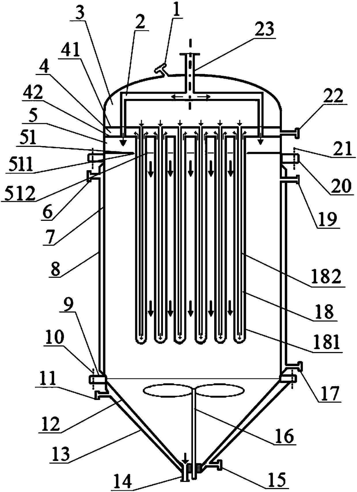
[0057] Embodiment 3, with reference to attached image 3 , 4 , 5a, 5b, 5c.

[0058] In this embodiment, the outer tube 181 of the inter-tube falling film support tube 18 is a straight tube with a constant diameter, and there is no horizontal inter-tube connecting wire between two adjacent inter-tube falling film support tubes.

[0059] Preferably, the ratio of the distance between the tubes of the falling film support tubes between adjacent tubes to the tube diameter is 0.1-10.

[0060] Other parts and implementation method of this embodiment are the same as embodiment 1, in image 3 , the reference numerals and figure 1 The same means the same meaning.


PUM

PropertyMeasurementUnit
diameteraaaaaaaaaa
diameteraaaaaaaaaa
diameteraaaaaaaaaa

Abstract

The invention discloses relates to a row-up pipe film falling melt phase polycondensation method for preparing high-viscosity melt and a reactor thereof. The row-up pipe film falling melt phase polycondensation method is characterized in that melt monomer blend or pre-polymer forms waterfall-type film falling flow among row-up inter-pipe film falling support pipes to realize melt polycondensation, melt falls off the pipes and gathers to the bottom of the reactor for further stirring and uniformizing, and materials are discharged after reaction. The reactor used in this method is of integral vertical structure and comprises a shell, a heating medium tank at the upper end, inter-pipe film falling support pipes connected with the heating medium tank, a material tank, a bottom shell at the lower end, and a blender and so on. The film falling support pipes with inner pipes inside are vertically hung and rowed up, and orifices are communicated with the heating medium tank for flowing of the heating medium. The reactor has the advantages of low flowing resistance, no dead corners, large filming area, and fast surface upgrading, and plug flow is realized. Moreover, the reactor is applicable to melt polycondensation of high-viscosity melt such as PET.

Description

technical field [0001] The invention relates to a falling film type melt polycondensation reaction method and melt polycondensation reaction equipment in the production of high-viscosity polymers. Background technique [0002] The polycondensation reaction is a reversible equilibrium reaction. With the progress of the polycondensation reaction, small molecular compounds need to be removed from the reaction system in a timely and effective manner, so that the molecular weight of the polymer is continuously increased, including polyethylene terephthalate (PET), poly Polypropylene terephthalate (PTT), polybutylene terephthalate (PBT), polyethylene naphthalate (PEN), polyamide (PA) and polycarbonate (PC), etc. The polymers are prepared by polycondensation reaction. The implementation methods of polycondensation reaction mainly include melt polycondensation, solid-state polycondensation, solution polycondensation, etc. Among them, melt polycondensation is widely used because of ...

Claims


Application Information

Patent Timeline
Patent Type & Authority Patents(China)
IPC IPC(8): B01J3/04B01J3/03B01J19/18B01J19/32
CPCB01J3/03B01J3/04B01J19/1887B01J19/32B01J2219/00085
Inventor 陈世昌陈文兴张先明马建平刘雄严旭明景辽宁
Owner ZHEJIANG SCI-TECH UNIV
Why Eureka
Try Eureka