Biogas slurry optical treatment breeding system and working method thereof

A breeding system and light treatment technology, applied in the field of biogas slurry treatment, can solve the problems of not very obvious removal effect, inability to absorb a large amount of biogas slurry, and difficult operation technology, so as to reduce feeding cost, improve reproductive effect, increase economic effect

Active Publication Date: 2016-08-17
江苏盐渎百鸣农业有限公司
View PDF9 Cites 8 Cited by
  • Summary
  • Abstract
  • Description
  • Claims
  • Application Information

AI Technical Summary

Problems solved by technology

[0004] The research on the purification method of biogas slurry mostly follows the urban sewage treatment method, using physical, chemical and biological methods, such as natural biological treatment methods such as biological pond method and artificial wetland, and industrialized treatment models using reactors such as MBR, SBR and reverse osmosis. However, due to the characteristics of high operating costs and difficult operation techniques, these methods are difficult to promote in farmers, and the above methods are not very effective in removing N and P in water. Therefore, after simple aeration treatment of biogas slurry Direct discharge is still the main treatment method at present
There are also some biogas slurry used for farmland irrigation, biogas slurry seed soaking, foliar spraying, soilless cultivation, etc., but due to transportation costs and application safety issues, the use of biogas slurry is very small and cannot be used for large-scale aquaculture. A large amount of biogas slurry produced by anaerobic fermentation, so direct discharge is still the main treatment method of biogas slurry

Method used


Image

  • Biogas slurry optical treatment breeding system and working method thereof

Examples


Embodiment Construction

[0033] The following are specific embodiments of the present invention and in conjunction with the accompanying drawings, the technical solutions of the present invention are further described, but the present invention is not limited to these embodiments.

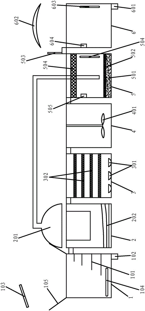
[0034] Such as figure 1 As shown, the biogas liquid light treatment aquaculture system includes a solid-liquid separation tank 1, a decomposition treatment tank 2, an aeration treatment tank 3, an acid-base adjustment tank 4, an algae cultivation tank 5 and an animal cultivation tank 6 arranged in the order of treatment processes , the solid-liquid separation pool 1, the decomposition treatment pool 2, the aeration treatment pool 3, the acid-base adjustment pool 4, the algae culture pool 5 and the animal culture pool 6 are connected in series end to end through the connection port; the solid-liquid separation pool 1 has a liquid inlet And the liquid outlet, the bottom of the liquid inlet is provided with a liquid inlet, an...


PUM


Abstract

The invention provides a biogas slurry optical treatment breeding system and a working method thereof. The biogas slurry optical treatment breeding system comprises a solid-liquid separation tank, a decomposition treatment tank, an aeration treatment tank, a pH value regulation tank, an algae culture tank and an animal raising tank which are sequentially arranged according to a treatment process. The solid-liquid separation tank, the decomposition treatment tank, the aeration treatment tank, the pH value regulation tank, the algae culture tank and the animal raising tank are sequentially connected in series end to end through connectors. The solid-liquid separation tank is used for carrying out sedimentation treatment and disinfection treatment on biogas slurry; the decomposition treatment tank is used for carrying out anaerobic and aerobic catabolism treatment on biogas slurry; the aeration treatment tank is used for carrying out aeration treatment on biogas slurry; the pH value regulation tank is used for carrying out supplementing and adjustment on the concentration, the pH value and the nutritive salt ingredient of biogas slurry; algae are cultured in the algae culture tank, and biogas slurry and biogas are utilized for providing nutrients for algae and are purified by algae; various aquatic animals are raised in the animal raising tank in an isolated mode, and main feed is provided for aquatic animals with algae. According to the biogas slurry optical treatment breeding system and the working method thereof, a cyclic and ecological culture industry is formed, and the environment is improved.

Description

technical field [0001] The invention belongs to the technical field of biogas slurry treatment, and relates to a biogas slurry purification cultivation system, in particular to a biogas slurry light treatment cultivation system and an operation method thereof. Background technique [0002] Biogas slurry, also known as "anaerobic fermentation liquid", is a water-soluble by-product remaining after anaerobic fermentation of organic matter such as animal manure and straw. With the adjustment of the agricultural industry structure and the construction of new countryside, the intensive livestock and poultry breeding industry has developed rapidly. As the product of biogas anaerobic fermentation, these waste liquids are used as agricultural fertilizers or directly discharged, and little consideration is given to whether the discharge meets the standards or not. Agricultural safety. In fact, after anaerobic digestion, the biogas slurry still contains a large amount of nitrogen, pho...

Claims


Application Information

Patent Timeline
IPC IPC(8): C02F9/14A01G33/00A01K63/00A01K63/04A01K63/06A23K50/80A23K10/30
CPCA01G33/00A01K63/00A01K63/003A01K63/04A01K63/042A01K63/047A01K63/06A01K63/065A01K61/10A01K61/40A01K61/51C02F1/02C02F1/32C02F1/50C02F1/52C02F1/66C02F1/76C02F3/301C02F3/32C02F3/322C02F3/327C02F7/00C02F9/00C02F2001/007C02F2201/009C02F2301/08C02F2303/04C02F2303/10C12M21/04C12M23/36C12P5/023Y02E50/30Y02W10/37Y02P60/20Y02P60/60Y02A40/80Y02A40/81
Inventor 王佳莺
Owner 江苏盐渎百鸣农业有限公司
Why Eureka
Try Eureka