Multifunctional composite thermal-insulating layer

A multi-functional, heat-insulating layer technology, applied in the direction of heat preservation, pipeline protection, and protection of pipelines through heat insulation, etc., can solve the problems of large heat loss, rising temperature of the outer surface of the insulating layer, and hidden safety hazards.

Active Publication Date: 2016-08-17
韩松
View PDF8 Cites 11 Cited by
  • Summary
  • Abstract
  • Description
  • Claims
  • Application Information

AI Technical Summary

Problems solved by technology

[0003] In the existing technology, traditional single thermal storage materials such as rock wool and aluminum silicate fiber are mainly used for pipe insulation. The single structure not only has poor thermal insulation performance, but also has a large heat loss, and such a structure can keep thermal insulation after 1-2 years of use. The effect drops rapidly, the temperature of the outer surface of the insulation layer gradually rises, and the heat loss is very serious, which not only increases the production cost, but also increases the load of the device, and there will be safety hazards in the long-term operation of the production device in this case

Method used


Image

  • Multifunctional composite thermal-insulating layer
  • Multifunctional composite thermal-insulating layer
  • Multifunctional composite thermal-insulating layer

Examples


Embodiment 1

[0049] Shougang steelmaking RH furnace superheated steam pipe insulation renovation project, pipe diameter DN325, length 906m, medium temperature 285 ℃, the experimental implementation steps are as follows:

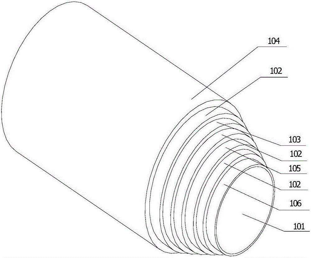
[0050] 1. Install a layer of isolation layer 106 of high-temperature-resistant emission material close to the pipeline or equipment substrate 101, and then install a layer of inner protective layer 102 containing pick fiber material. The thickness of the inner protective layer is controlled at 12mm, and the thickness of the isolation layer is controlled at 1mm;

[0051] 2. Install the full normal emissivity according to the temperature between the inner protective layer and the insulation layer. Select the emission layer 105 of the heat barrier emission glass with a thickness of 50mm. Cut into multiple insulation tiles according to the surface shape of the thermal equipment and the pipeline, and overlap each other. direct connection;

[0052]3. Install an inner protectiv...

Embodiment 2

[0057] 30WM unit main steam pipe insulation renovation project, pipe diameter DN325, length 170m, medium temperature 545°C, the experimental implementation steps are as follows:

[0058] 1. Install the isolation layer 106 of high-temperature-resistant emission material close to the pipeline or equipment substrate 101, and then install the inner protective layer 102 of crystal fiber. The thickness of the inner protective layer is controlled at 12mm to serve as a protective layer between the pipeline substrate and the insulation layer. Thermal expansion and decompression and shock absorption, supporting the overall insulation structure from collapsing, to protect the pipeline matrix and insulation layer, the thickness of the isolation layer is controlled at 100mm and divided into three layers of painting;

[0059] 2. According to the outer surface temperature of the first inner protection layer 102, install a layer of calcium silicate insulation layer 103, the thickness of the in...

Embodiment 3

[0066] Beijing Thermal Power Group Co., Ltd. Yuetan Unicom line main line reconstruction project, pipe diameter DN720, length 3920m, medium temperature 103 ℃, the experimental implementation steps are as follows:

[0067] 1. Install the insulating layer 106 of high-temperature-resistant emissive material close to the pipeline or equipment substrate 101, and then install the inner protective layer 102 of airgel. The thickness of the inner protective layer is controlled at 2 mm as a protective layer between the pipeline substrate and the insulation layer Absorb thermal expansion and decompression and shock absorption, support the overall insulation structure from collapsing, so as to protect the pipeline substrate and insulation layer, the thickness of the isolation layer is controlled at 80mm and divided into two layers, which are attached to the surface of the pipeline or equipment substrate by surface melting;

[0068] 2. According to the temperature of the outer surface of th...


PUM

PropertyMeasurementUnit
thicknessaaaaaaaaaa
thicknessaaaaaaaaaa
thicknessaaaaaaaaaa

Abstract

The invention provides a multifunctional composite thermal-insulating layer which comprises a pipe or an equipment base, at least one thermal-insulating layer, at least one internal protective layer, and at least one isolating layer. The internal protective layer is used for absorbing swell and supporting the whole thermal-insulating structure to prevent the same from collapsing. The isolating layer made of a high-temperature-resistant emitting material has effects of corrosion resistance and air-tightness, and further has effects of reducing heat-transfer coefficient and thermal conductivity of metal materials, isolating heat conduction and thermal bridge of pipe supports and hangers and improving heat barriers. Specifically, the isolating layers, the internal protective layers and the thermal-insulating layers are sequentially arranged on the outer side of the pipe or equipment base; the internal protective layers and the thermal-insulating layers are composited and interactive with each other, are arranged alternatively to overcome heat loss caused by irradiation, conduction and convection; joints of the different layers are staggered with one another to realize non-convection heat dissipation; and every two adjacent layers are made from different materials. The multifunctional composite thermal-insulating layer solves the problems about heat loss caused by irradiation, conduction and convection.

Description

technical field [0001] The invention relates to the field of heat preservation of pipes and equipment, in particular to a multifunctional composite heat preservation layer. Background technique [0002] Nowadays, steel mills, power plants, petrochemical plants and many production enterprises have many pipelines on production equipment, so taking good insulation measures for pipelines not only has the practical significance of saving energy and reducing consumption, but also reduces production costs from the source. So as to achieve the purpose of energy saving and emission reduction. When selecting pipeline insulation materials, in addition to considering the thermal conductivity of the material, the water absorption rate, combustion performance, strength and other indicators of the material should also be considered. [0003] In the existing technology, traditional single thermal storage materials such as rock wool and aluminum silicate fiber are mainly used for pipe insul...

Claims


Application Information

Patent Timeline
Patent Type & Authority Applications(China)
IPC IPC(8): F16L59/14F16L59/04F16L59/02
CPCF16L59/029F16L59/04F16L59/14
Inventor 韩松
Owner 韩松
Why Eureka
Try Eureka