Reflective type high-speed camera shooting schlieren system applied to constant volume combustion bomb and capable of correcting chromatic aberration

A constant-volume incendiary bomb and high-speed camera technology, applied in optical components, optics, instruments, etc., can solve the problems of unstable light effects, affecting experimental accuracy, and high power consumption, etc., to achieve convenient and arbitrary movement, good optical fiber flexibility, The effect of not getting hot

Inactive Publication Date: 2016-08-17
WUHAN UNIV OF TECH
8 Cites 5 Cited by

AI-Extracted Technical Summary

Problems solved by technology

[0003] The traditional reflective constant volume incendiary bomb high-speed camera schlieren system uses halogen tungsten lamp or xenon lamp as the light source, which consumes a lot of power and produces a lot of heat. If the heat dissipation is not good, it is easy to light decay, which makes the output light effect unstable. Experimental accuracy, and the high heat generated at the same time will easily deform the condenser lens behind and affect the experimental accuracy
In addition, since the light sources used in the laboratory are all polychromatic light, the condenser lens in the traditional reflective constant volume incendiary bomb high-speed camera schlieren system uses a spherical convex lens. The difference ...

Method used

In technique scheme, condenser lens group 3 is installed in condenser lens group lens barrel 14, and condenser lens group lens barrel 14 comprises the first convex lens lens barrel 14.1, the first concave lens lens barrel 14.2 and the second convex lens lens barrel 14.3; The first convex lens One end inner ring of the lens barrel 14.1 is provided with a first annular groove 15.1 for fitting the first convex lens 12.1, the first concave lens lens barrel 14.2 is provided with an inner cavity 16 for fixing the first concave lens 13.1 along the axial direction, and the second convex lens mirror One end inner circle of the barrel 14.3 is provided with a second annular groove 15.2 for fitting the second convex lens 12.2; one end of the first concave lens barrel 14.2 is threadedly connected with the first convex lens barrel 14.1 having the first annular groove 15.1 , the other end of the first concave lens barrel 14.2 is threadedly connected to the second end of the second convex lens barrel 14.3 having the second annular groove 15.2. Each lens is installed in its corresponding lens barrel, and each lens ...

Abstract

The invention discloses a reflective constant-volume incendiary bomb high-speed camera schlieren system capable of correcting chromatic aberration, which comprises a light source, an optical fiber, a condenser lens group, a slit device, a first reflector, a collimating mirror, a constant-volume Incendiary bomb, schlieren mirror, second reflector, knife edge and high-speed camera, the optical input end of the optical fiber is connected to the light source, the optical output end of the optical fiber is connected to the condenser lens group, and the focus of the condenser lens group is connected to the collimating lens The focal points reflected by the first reflecting mirror coincide at the slit device, and the knife edge is located at the focal point of the schlieren mirror reflected by the second reflecting mirror. The present invention adopts the condenser lens group to improve the existing condenser lens, and corrects the chromatic aberration produced by the polychromatic light after passing through the lens, so that the real spherical flame propagation photos in the constant-volume incendiary bomb can be obtained more accurately.

Application Domain

Technology Topic

High speed videoOptical path +6

Image

  • Reflective type high-speed camera shooting schlieren system applied to constant volume combustion bomb and capable of correcting chromatic aberration
  • Reflective type high-speed camera shooting schlieren system applied to constant volume combustion bomb and capable of correcting chromatic aberration
  • Reflective type high-speed camera shooting schlieren system applied to constant volume combustion bomb and capable of correcting chromatic aberration

Examples

  • Experimental program(1)

Example Embodiment

[0020] The present invention will be further described in detail below in conjunction with the drawings and specific embodiments.
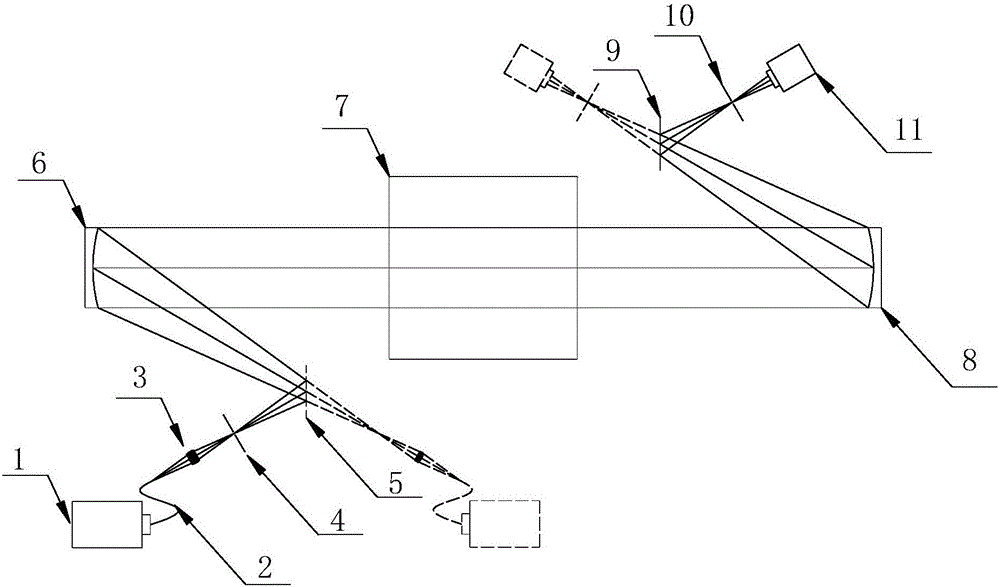
[0021] The reflective constant volume incendiary high-speed imaging schlieren system shown in the figure that can correct chromatic aberration includes a light source 1, an optical fiber 2, a condenser lens group 3, a slit device 4, a first mirror 5, and a collimator arranged in sequence along the optical path. Mirror 6, constant volume incendiary bomb 7, schlieren mirror 8, second reflector 9, knife edge 10 and high-speed camera 11; light source 1 is an LED-light source, the light input end of fiber 2 is connected to light source 1, and the light output of fiber 2 The end is connected to the condenser lens group 3. The focal point of the condenser lens group 3 and the focal point of the collimator lens 6 after being reflected by the first mirror 5 coincide at the slit device 4, so that the size of the light source can be adjusted by adjusting the aperture of the slit device 4 , It can also be more convenient and more accurate to determine the focus of the condenser lens group when debugging the schlieren system. The knife edge 10 is located at the focal point of the schlieren mirror 8 after being reflected by the second reflector 9. This can be adjusted by adjusting the aperture of the knife edge 10. The size of the image finally projected into the high-speed camera 11 is determined.
[0022] In the above technical solution, the condenser lens group 3 is composed of a first convex lens 12.1, a first concave lens 13.1, and a second convex lens 12.2 arranged in sequence along the optical path. The distance between the first convex lens 12.1, the first concave lens 13.1, and the second convex lens 12.2 Adjustable, so by adjusting the distance of the first convex lens 12.1, the first concave lens 13.1, and the second convex lens 12.2 to correct the chromatic aberration caused by the light emitted by different light sources.
[0023] In the above technical solution, the condenser lens group 3 is installed in the condenser lens barrel 14. The condenser lens barrel 14 includes a first convex lens barrel 14.1, a first concave lens barrel 14.2 and a second convex lens barrel 14.3; a first convex lens barrel 14.1 One end of the inner ring is provided with a first annular groove 15.1 for fitting the first convex lens 12.1, the first concave lens barrel 14.2 is provided with an inner cavity 16 for fixing the first concave lens 13.1 along the axial direction, and the second convex lens barrel 14.3 One end of the inner ring is provided with a second annular groove 15.2 for inserting the second convex lens 12.2; one end of the first concave lens barrel 14.2 is connected with the end of the first convex lens barrel 14.1 having the first annular groove 15.1 through a thread, the first The other end of the concave lens barrel 14.2 and the end of the second convex lens barrel 14.3 having the second annular groove 15.2 are connected by threads. Install each lens in its corresponding lens barrel. Each lens barrel is connected by threads, and the degree of screwing between the lens barrels is used to correct the chromatic aberration in different situations, so as to avoid direct contact with the mirror surface and dirty mirror surface during lens adjustment. , While adjusting the distance between the mirrors can also be more stable. What is important is that in the condenser lens group, when the convex lens barrel is completely screwed into the concave lens barrel, the distance between the convex lens and the concave lens is equal to 0 at this time.
[0024] In the above technical solution, the first annular groove 15.1, the second annular groove 15.2 and the inner cavity 16 are all provided with an annular stop ring 17, and the annular stop ring 17 is fixed to prevent the lens from being scratched or crushed. , And easy to clean and replace the lens.
[0025] In the above technical solution, the slit device 4 is an annular slit device with adjustable aperture. When the focal point of the condenser lens group 3 is determined, the aperture of the slit device 4 is adjusted to 0, and when projected onto the slit device 4, a bright The position of the slit device 4 is the focal plane of the condenser lens group 3.
[0026] The working process of the present invention: firstly, the light emitted by the light source 1 is transmitted to the condenser lens group 3 through the optical fiber 2, and the distance between the lenses of the condenser lens group 3 is adjusted so that it is finally projected on the slit device 4 and there is no color in the outermost circle of the light. The aperture of the slit device 4 is adjusted to 0, and the distance between the slit device 4 and the condenser lens group 3 is adjusted so that the slit device 4 is a bright spot. At this time, the surface of the slit device 4 is The focal plane of the condenser lens group 3, the slit device 4 is a point light source; then, the point light source is emitted from the focal point of the condenser lens group 3, reflected by the first mirror 5, and then projected to the collimating lens 6, after collimation The light reflected by the mirror 6 forms a uniformly mixed color parallel light and is projected into the constant volume combustion bomb 7; then, the measured area in the constant volume combustion bomb 7 burns to form a spherical flame, the fluid is disturbed, the refractive index changes, and the parallel light passes through the The measurement area reaches the schlieren mirror 8, the light reflected by the schlieren mirror 8 passes through the knife edge 10 after being reflected by the second mirror 9, and finally forms an image on the high-speed camera 11.
[0027] The above are only specific embodiments of the present invention. It should be pointed out that any changes or substitutions that can be easily conceived by those skilled in the art within the technical scope disclosed by the present invention should be covered by the protection scope of the present invention. within.

PUM

no PUM

Description & Claims & Application Information

We can also present the details of the Description, Claims and Application information to help users get a comprehensive understanding of the technical details of the patent, such as background art, summary of invention, brief description of drawings, description of embodiments, and other original content. On the other hand, users can also determine the specific scope of protection of the technology through the list of claims; as well as understand the changes in the life cycle of the technology with the presentation of the patent timeline. Login to view more.

Similar technology patents

Classification and recommendation of technical efficacy words

  • Low energy consumption
  • Not easy to get hot

Method for extracting flavonoids from ginkgo biloba leaves with deep eutectic solvent

InactiveCN104887723AReduce lossLow energy consumptionGinkgophyta medical ingredientsChemistryLiquid–liquid extraction
Owner:TIANJIN UNIVERSITY OF TECHNOLOGY

Motor driving device and system

PendingCN106849827AStrong current flow capabilityNot easy to get hotElectric motor controlMechanical engineeringControl engineering
Owner:GUILIN UNIVERSITY OF TECHNOLOGY

Novel reciprocating magnet pulse motor

PendingCN108233599ANot easy to get hotGood magnetic energy utilizationMechanical energy handlingClutchMagnetic energy
Owner:余建华

Anti-vibration and anti-shock power slow-start module and electronic equipment

PendingCN108599542ANot easy to get hotIncrease the rated currentConversion constructional detailsOxide semiconductorElectronic communication technology
Owner:SHENZHEN ZHENHUA FU ELECTRONICS +1
Why Eureka
Try Eureka