Wastewater treatment device with coupled Electro-Fenton and electrocatalytic oxidation without solid waste generation

An electrocatalytic oxidation and wastewater treatment technology, which is applied in water/sewage treatment, water/sewage multi-stage treatment, water/sludge/sewage treatment, etc. It can solve the problem of high treatment cost, large consumption of chemicals, waste of cathode energy, etc. problem, to achieve the effect of good treatment effect, improved energy efficient utilization, and improved degradation depth

Active Publication Date: 2016-08-24
南京赛佳环保实业有限公司
View PDF6 Cites 20 Cited by
  • Summary
  • Abstract
  • Description
  • Claims
  • Application Information

AI Technical Summary

Problems solved by technology

[0010] There are two fatal problems in Fenton's method in practical engineering applications, making it difficult to be widely used
First, the Fenton method requires the addition of Fe on-site 2+ and H 2 o 2 , the consumption of chemicals is large, and the processing cost is high
The second problem is more prominent. According to formula (1), a large amount of ferric ions are produced in the Fenton reaction process, which eventually turns into iron oxide with organic matter adsorbed on the surface and becomes solid waste (hazardous waste) that pollutes the environment. This is A large end of the current existence of Fenton and Electro-Fenton methods
[0011] The electrocatalytic oxidation treatment of wastewater is mainly carried out at the anode of the electrolytic equipment. In most cases, hydrogen evolution is the main cathode reaction of the electrolytic cell. The energy on the cathode is wasted needlessly, which leads to the problem of large energy consumption in the electrocatalytic oxidation technology.

Method used


Image

  • Wastewater treatment device with coupled Electro-Fenton and electrocatalytic oxidation without solid waste generation

Examples


Embodiment Construction

[0032] The present invention will be described in further detail below in conjunction with the accompanying drawings and embodiments.

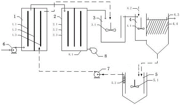
[0033] Such as figure 1 As shown, a wastewater treatment device coupled with solid waste electricity Fenton and electrocatalytic oxidation, including sequentially connected raw water pump 6, first diaphragm electrolyzer 1, second diaphragm electrolyzer 2, and Fenton reaction tank 3 , coagulation sedimentation tank 4 and iron slime dissolution tank 5,

[0034]The first diaphragm electrolytic cell 1 includes a first anode 1.1, a first diaphragm 1.2 and a first cathode 1.3, the first diaphragm 1.2 is located in the middle of the first electrolytic cell 1, and the first anode 1.1 and the first cathode 1.3 are respectively located in the first diaphragm The two sides of 1.2 form an anode chamber and a cathode chamber, and the upper and lower ends of the anode chamber and the cathode chamber are not connected; in the first diaphragm electrolytic ce...


PUM


Abstract

The invention relates to a wastewater treatment device with coupled Electro-Fenton and electrocatalytic oxidation without solid waste generation. The wastewater treatment device comprises a raw water pump, a first diaphragm electrolytic cell, a second diaphragm electrolytic cell, a Fenton reaction tank, a coagulating sedimentation tank and an iron cement dissolving tank which are connected in sequence, wherein the anode chambers of the first diaphragm electrolytic cell and the second diaphragm electrolytic cell are adopted for electrocatalytic oxidation reaction to dissolve organic pollutants; Fe<+3> generated after Fenton reaction is reduced into Fe<+2> in the cathode chamber of the first diaphragm electrolytic cell; H2O2 is generated through electrochemical synthesis in the cathode chamber of the second diaphragm electrolytic cell; the reduced Fe<+2>, the newly generated H2O2 and wastewater are fed into the reaction tank for Fenton reaction; the effluent is subjected to iron cement separation in the coagulating sedimentation tank; treated water is discharged; the sedimentary iron cement is Fe<+3> which is fed into the iron cement dissolving tank; after acid dissolution, the sedimentary iron cement is fed into the cathode chamber of the first diaphragm electrolytic cell and is circulated after electrochemical reduction; and therefore, solid waste production and emission are avoided.

Description

technical field [0001] The invention relates to a waste water treatment device, which is suitable for the treatment of high-concentration refractory organic waste water and belongs to the technical field of waste water treatment. Background technique [0002] The Fenton reaction is named after the discovery of the French scientist Fenton. The Fenton reagent method is to add the Fenton reagent in the acidic solution: hydrogen peroxide (H 2 o 2 ) and ferrous ions (Fe 2+ ), the Fenton reaction occurs when the two are in contact, generating hydroxyl radicals (OH), the reaction is as follows: [0003] h 2 o 2 +Fe +2 →2·OH+Fe +3 (1) [0004] If the H in Fenton's reagent 2 o 2 and Fe +2 It is produced on-site by electrochemical method, which is called electro-Fenton reaction. [0005] The electrocatalytic oxidation wastewater treatment process is mainly an anodic oxidation reaction, and organic pollutants are oxidized directly and indirectly at the anode. The anode in ...

Claims


Application Information

Patent Timeline
Patent Type & Authority Applications(China)
IPC IPC(8): C02F9/06C02F101/30
CPCC02F1/4672C02F1/52C02F1/725C02F9/00C02F2101/30
Inventor 蔡乃才刘秀宁梁晶陈晓春刘钟宁何书铭
Owner 南京赛佳环保实业有限公司
Why Eureka
Try Eureka