Ultrasonic assisting high-sensitivity detection system for pollutants in fluid and working method of ultrasonic assisting high-sensitivity detection system

An ultrasonic-assisted detection system technology, applied in the analysis of gas mixtures, measuring devices, particle size analysis, etc., can solve the problems of poor accuracy, poor consistency, and high price, and achieve enhanced fine particle concentration, improved detection accuracy, and good reliability Effect

Inactive Publication Date: 2016-08-24
NANJING UNIV OF AERONAUTICS & ASTRONAUTICS
View PDF4 Cites 7 Cited by
  • Summary
  • Abstract
  • Description
  • Claims
  • Application Information

AI Technical Summary

Problems solved by technology

[0003] At present, mature pollutant detection sensors include semiconductor, electrochemical, optical, etc. Among them, semiconductor sensors have long life and low price, but have poor consistency and poor accuracy.
Electrochemical sensors have average accuracy and short life
Optical sensors are accurate but expensive

Method used


Image

  • Ultrasonic assisting high-sensitivity detection system for pollutants in fluid and working method of ultrasonic assisting high-sensitivity detection system
  • Ultrasonic assisting high-sensitivity detection system for pollutants in fluid and working method of ultrasonic assisting high-sensitivity detection system

Examples


Embodiment 1

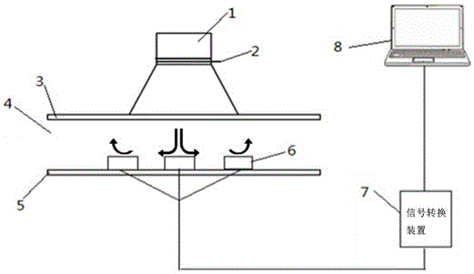
[0034] refer to figure 1, the ultrasonic transducer 1 is fixedly placed in the air environment with a bracket, when the excitation is applied to the electrode 2, the ultrasonic transducer 1 will generate vibration at the same frequency as the excitation, and the vibration will be amplified and transmitted through the sound radiation plate 3, and the radiation will be The sound field is generated in layer 4, and the pollutants in the radiation layer are moved by the sound field and the acoustic flow and acoustic vibration generated by it, and gather in a fixed area. The sensor 6 is placed at the position with the strongest acoustic flow and acoustic vibration effect to detect pollutants. Then, the signal processing conversion device 7 collects the induction signal in the sensor 6 and converts the signal into a signal recognized by the computer, and transmits it to the computer 8. Finally, the computer 8 calculates the corresponding position pollutant concentration according to t...

Embodiment 2

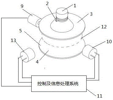
[0036] refer to figure 2 , the ultrasonic transducer 1 is fixedly placed in the air environment with a bracket, when the excitation is applied to the electrode 2, the ultrasonic transducer 1 will generate vibration at the same frequency as the excitation, and the vibration will be amplified and transmitted through the sound radiation plate 3, and the radiation will be The sound field is generated in the layer 4 and forms the nodal plane 12 of the sound field, and the fine particles in the radiation layer 4 gather near the nodal plane 12 of the sound field under the action of the acoustic radiation force, and then the laser emitting device 9 is placed where the emitting laser can pass through the nodal plane 12 of the sound field The position on one side of the radiation layer 4, the transmitted light receiving device 10 is arranged on the corresponding side of the laser emitting device 9, and the scattered light receiving device 13 is arranged on the front or rear of the radia...


PUM


Abstract

The invention discloses an ultrasonic assisting high-sensitivity detection system for pollutants in fluid and a working method of the ultrasonic assisting high-sensitivity detection system. The ultrasonic assisting high-sensitivity detection system comprises an ultrasonic transducer. The ultrasonic transducer is provided with electrodes, an acoustic radiation plate is fixedly arranged on the surface of the ultrasonic transducer, a reflection plate is arranged below the acoustic radiation plate, a radiation layer is formed between the acoustic radiation plate and the reflection plate, and a sensor is arranged at the radiation layer and connected with a computer through a signal processing conversion device. A laser irradiation device and a transmission light receiving device are symmetrically arranged on the left side and the right side outside the radiation layer, and a scattered light receiving device is arranged in the front of the radiation layer or on the back of the radiation layer. The laser irradiation device, the transmission light receiving device and the scattered light receiving device are connected with a control and information processing system. The system utilizes acoustic flow, acoustic radiation pressure and acoustic vibration produced by resonance of the ultrasonic transducer and can not damage components of the pollutants, the detection precision of the sensor and a laser fine particle detection device can be improved exponentially, cost is greatly reduced, and the detection precision is greatly improved.

Description

technical field [0001] The invention relates to an ultrasonic-assisted high-sensitivity detection system for pollutants in a fluid and its working method, in particular to a principle of gathering pollutants based on ultrasonic vibration of an ultrasonic transducer and its generated acoustic flow and acoustic radiation force, which belongs to the ultrasonic application field. Background technique [0002] With the development of industry and agriculture and the increase of motor vehicles, air and water pollution are becoming more and more serious. Air and water pollutants are complex, including heavy metals, bacteria, respirable dust, pesticides and antibiotics. How to quickly and economically detect various pollutants has become a difficult problem in environmental governance, and a high-efficiency, low-cost, easy-to-implement and non-polluting detection method is urgently needed. [0003] At present, mature pollutant detection sensors include semiconductor, electrochemic...

Claims


Application Information

Patent Timeline
Patent Type & Authority Applications(China)
IPC IPC(8): G01N33/00G01N15/06G01N15/02
CPCG01N15/0205G01N15/06G01N33/0004G01N2015/0693
Inventor 胡俊辉苏松飞彭榆善钟思恒
Owner NANJING UNIV OF AERONAUTICS & ASTRONAUTICS
Why Eureka
Try Eureka