General spacecraft ground test bed system

A technology for ground testing and spacecraft, applied in general control systems, control/adjustment systems, instruments, etc., can solve problems such as missing the best time and conditions for discovery and problem solving, short development cycle, and affecting test progress, etc., to achieve The effective test time ratio is improved, the electrical performance consistency is high, and the test coverage rate is improved.

Active Publication Date: 2016-08-24
BEIJING SPACE TECH RES & TEST CENT
View PDF9 Cites 19 Cited by
  • Summary
  • Abstract
  • Description
  • Claims
  • Application Information

AI Technical Summary

Problems solved by technology

[0003] The traditional comprehensive testing technology has low test efficiency, long test cycle, takes up a lot of human resources, and the test progress is difficult to control. The main reasons are:
[0004] a. Sufficient testing at the stand-alone level and sub-system level, insufficient effectiveness, uncontrolled status, delaying the problem to the comprehensive testing stage, and missing the best time and conditions for finding and solving the problem;
[0005] b. The state of joint debugging between subsystems is not controlled, and the sufficiency and effectiveness of joint debugging are difficult to guarantee
After joint debugging, it is impossible to control the subsystem to change the interface status, and problems will still be found in the comprehensive test;
[0006] c. The sub-system acceptance test is only a static test and lacks effective acceptance checks. Various problems at the stand-alone level and sub-system level are introduced into the comprehensive test, which makes troubleshooting difficult and affects the efficiency of the later comprehensive test;
[0007] d. The delivery time of some sub-system products is late, and the products delivered first can only be stored, resulting in a late start time of the comprehensive test and affecting the overall progress of the test;
[0008] e. The traditional comprehensive test mode is only based on insufficient telemetry information, and it is difficult to create and apply sufficient test incentives. The observability and controllability of the test are not good, so that the design of the test plan is subject to many constraints, and many test items are difficult to implement. The test adequacy and coverage are insufficient, the information resources available for test evaluation are also insufficient, and there is also a lack of information required for troubleshooting when problems occur;
[0009] f. Due to the inability to guarantee the correctness of the equipment status of the sub-systems and the late start of the comprehensive testing work, the comprehensive testing of the whole device will be carried out directly after the final assembly work is completed. Personnel are in an invalid waiting state, affecting the progress of later testing;
[0010] g. Due to the inconvenient disassembly and assembly of the equipment in the complete state, the available technical means for troubleshooting are limited. On the one hand, troubleshooting and equipment disassembly will interrupt and delay the comprehensive test process; The progress of retesting and retesting is under great pressure, and it is easy to leave hidden dangers;
[0011] According to my country's spacecraft development plan, my country's spacecraft will be intensively developed and launched in the future, with stricter quality requirements, a shorter development cycle, and fewer R&D personnel assigned to each spacecraft. The above characteristics have brought new challenges to the comprehensive test of spacecraft. The needs and challenges of the traditional comprehensive testing technology must be transformed and innovated to meet the needs of the development of my country's aerospace new era

Method used


Image

  • General spacecraft ground test bed system
  • General spacecraft ground test bed system
  • General spacecraft ground test bed system

Examples


Embodiment Construction

[0039] The present invention will be described in detail below in conjunction with the accompanying drawings and specific embodiments.

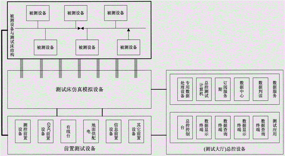
[0040] Such as figure 1 As shown, the general spacecraft ground test bed system of the present invention includes a test bed structure, test bed simulation equipment, front-end test equipment and general control equipment located in the test hall.

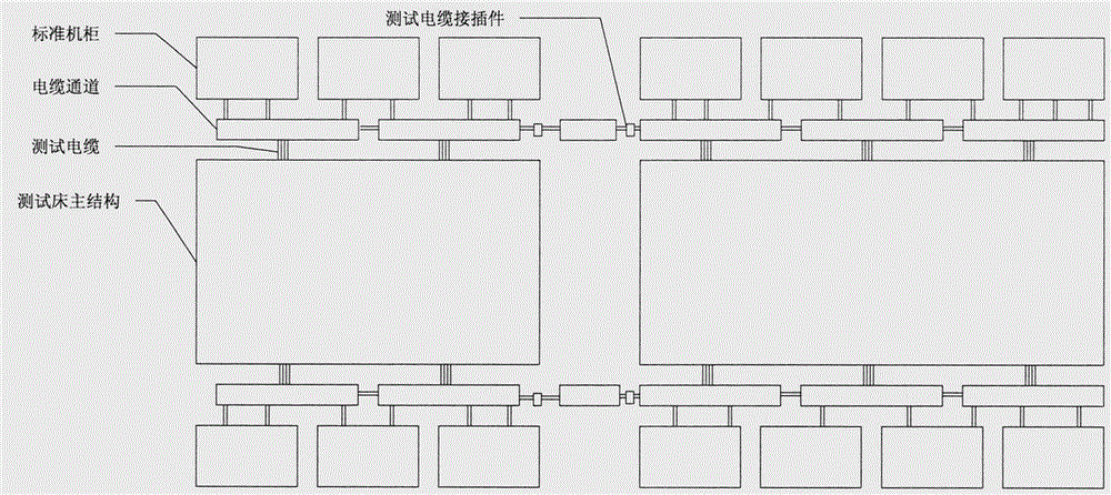
[0041] Such as figure 2 As shown, the structure of the test bed is a simple cabin structure, and an open frame cabinet that can be freely disassembled and combined is used to replace the real cabin structure. A set of test cables consistent with the design state can be used to carry, load, and Operate and connect electrical equipment under test and monitoring equipment dedicated to testing. The installation method of the equipment under test refers to the actual installation layout of the equipment in the cabin to ensure that the installation orientation of the equipment is similar to the actua...


PUM


Abstract

The present invention provides a general spacecraft ground test bed system. The system comprises a test bed structure; a test bed simulation device configured to realize the general simulation of electric interfaces, electrical property equivalence of a dynamo-electric device, onboard flight environment simulation and the electrical interface simulation of an external system; a preposition test device; and a general control device located at a testing hall. The test bed structure employs freely splitting and combining open-type framework rack, and the open-type framework rack employs a bearing rod, an installing plate and a bearing rod joint. The test bed simulation device comprises a 1553B bus simulator, a power supply and distribution simulator, an Ethernet communication simulator and a simulation service and controller. The general spacecraft ground test bed system is able to develop a system-grade test prior to the completion of single unit equipment so as to conveniently and effectively discover abnormal single units having dismounting problems and process the low hierarchy problem of the single unit and the subsystem, cover various normal and fault flight modes, and reduce manpower resource consumption.

Description

technical field [0001] The invention belongs to the field of spacecraft electrical performance testing, in particular to a general spacecraft ground test bed system suitable for integrated verification and testing of spacecraft system electrical performance design. Background technique [0002] Comprehensive testing is an important task in spacecraft system integration and system verification, and it is the last link to ensure the quality of spacecraft development and manufacturing. [0003] The traditional comprehensive testing technology has low test efficiency, long test cycle, takes up a lot of human resources, and the test progress is difficult to control. The main reasons are: [0004] a. Sufficient testing at the stand-alone level and sub-system level, insufficient effectiveness, uncontrolled status, delaying the problem to the comprehensive testing stage, and missing the best time and conditions for finding and solving the problem; [0005] b. The state of joint deb...

Claims


Application Information

Patent Timeline
Patent Type & Authority Applications(China)
IPC IPC(8): G05B17/02
Inventor 冻伟东胡骏张强潘顺良
Owner BEIJING SPACE TECH RES & TEST CENT
Why Eureka
Try Eureka