A method and device for testing the resistance in the thickness direction of a composite thin film material
A technology of composite film and material thickness, which is applied in measurement devices, measurement of resistance/reactance/impedance, measurement of electrical variables, etc., can solve problems such as inability to eliminate point pressure, large error margin of measurement results, and distortion of material resistance judgment, to avoid Effects of concentrated pressure and mechanical piercing
- Summary
- Abstract
- Description
- Claims
- Application Information
AI Technical Summary
Problems solved by technology
Method used
Image
Examples
Embodiment 1
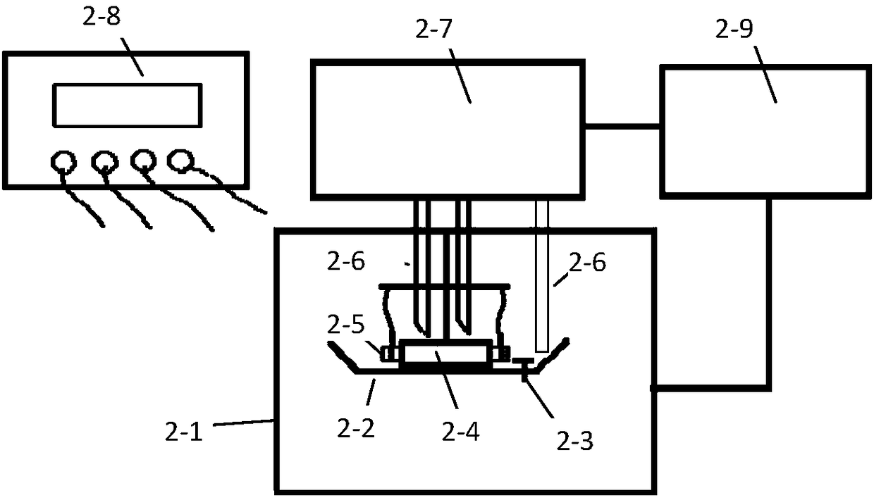
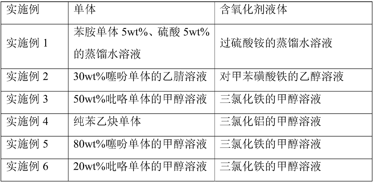
[0016]Example 1 The composite thin film material to be tested is the positive pole piece of lithium ion battery (a mixed coating of composite adhesive on both sides of aluminum foil, positive electrode material, conductive agent and other materials), and the pole piece to be tested is cut into a strip sample of 10 × 100mm Several, take two sample stacks: the overlapping area of the sample is 10×90mm, leave 10mm on the left and right to lead out the tabs, sandwich a piece of fiber paper with a length of 5mm×width 1mm×thickness 0.2mm between the overlapping surfaces of the two samples, two Add a piece of smooth glass sheet with length 90×width 15×thickness 2mm on the outside of the sample to clamp the sample pair in the middle, and then clamp the outer glass sheet with a clamp to make the sample pair 1 to be tested. After lamination is completed, the conductive polymer layer will be formed according to the types of monomer solution and oxidant-containing liquid shown in Table 1...
Embodiment 2
[0017] Example 2 The composite film material to be tested is a supercapacitor pole piece (a mixed coating of composite adhesives on both sides of aluminum foil and electrode materials, conductive agents, etc.), and the pole piece to be tested is cut into Φ20mm discs with 10×5mm rectangles to draw out There are several samples of the ear, and two sample stacks are taken: the overlapping part of the sample is a Φ20mm circular piece, and a piece of Φ25mm circular fiber paper is sandwiched between the overlapping surfaces of the two samples, and a piece of length 22× is added to the outside of the two samples A smooth ceramic sheet with a width of 22 x a thickness of 1 mm sandwiches the sample pair in the middle, and then clamps it on the outer glass sheet with a clamp to make the sample pair 2 to be tested. After lamination is completed, the conductive polymer layer will be formed according to the types of monomer solution and oxidant-containing liquid shown in Table 1, and the im...
Embodiment 3
[0018] Example 3 The composite film material to be tested is an aluminum-carbon composite foil for the negative electrode of a solid aluminum electrolytic capacitor (composite carbon layers on both sides of the aluminum foil). The area is 10×90mm, leaving 10mm on the left and right to lead out the tabs, sandwiching a layer of 12×95mm fiber paper between the overlapping surfaces of the two samples, and then adding a piece of 90×width 15×thick 2mm fiber paper on the outside of the two samples The smooth tile sandwiches the sample pair in the middle, and then clamps it on the outer ceramic tile with a clamp to make the sample pair 3 to be tested. After lamination is completed, the conductive polymer layer will be formed according to the types of monomer solution and oxidant-containing liquid shown in Table 1, and the immersion-polymerization procedure shown in Table 2. After the synthesis is completed, use a resistance meter to test the resistance of the two lead tabs.
PUM
| Property | Measurement | Unit |
|---|---|---|
| electrical conductivity | aaaaa | aaaaa |
Abstract
Description
Claims
Application Information
 - R&D
- Intellectual Property
- Life Sciences
- Materials
- Tech Scout
- Unparalleled Data Quality
- Higher Quality Content
- 60% Fewer Hallucinations
Browse by: Latest US Patents, China's latest patents, Technical Efficacy Thesaurus, Application Domain, Technology Topic, Popular Technical Reports.
© 2025 PatSnap. All rights reserved.Legal|Privacy policy|Modern Slavery Act Transparency Statement|Sitemap|About US| Contact US: help@patsnap.com


