Method for producing optical fiber preform and method for producing optical fiber

An optical fiber preform and a manufacturing method technology, applied in the field of optical fiber manufacturing, can solve problems such as inability to uniformly dope chlorine, inability to fully dehydrate, and characteristic deviation

Inactive Publication Date: 2016-08-31
FURUKAWA ELECTRIC CO LTD
View PDF8 Cites 8 Cited by
  • Summary
  • Abstract
  • Description
  • Claims
  • Application Information

AI Technical Summary

Problems solved by technology

[0008] However, when the bulk density of the porous preform is increased, in the known dehydration process, there is a problem that dehydration may not be performed sufficiently or chlorine may not be uniformly doped.
If the dehydration process is insufficient or the doping amount of chlorine is not uniform, variations in characteristics will occur in the bare fiber of the optical fiber manufactured by drawing the optical fiber preform
[0009] In particular, if the dehydration process is insufficient, it will greatly affect the loss at a wavelength of 1385nm in the manufactured optical fiber

Method used


Image

  • Method for producing optical fiber preform and method for producing optical fiber
  • Method for producing optical fiber preform and method for producing optical fiber
  • Method for producing optical fiber preform and method for producing optical fiber

Examples


no. 1 approach 〕

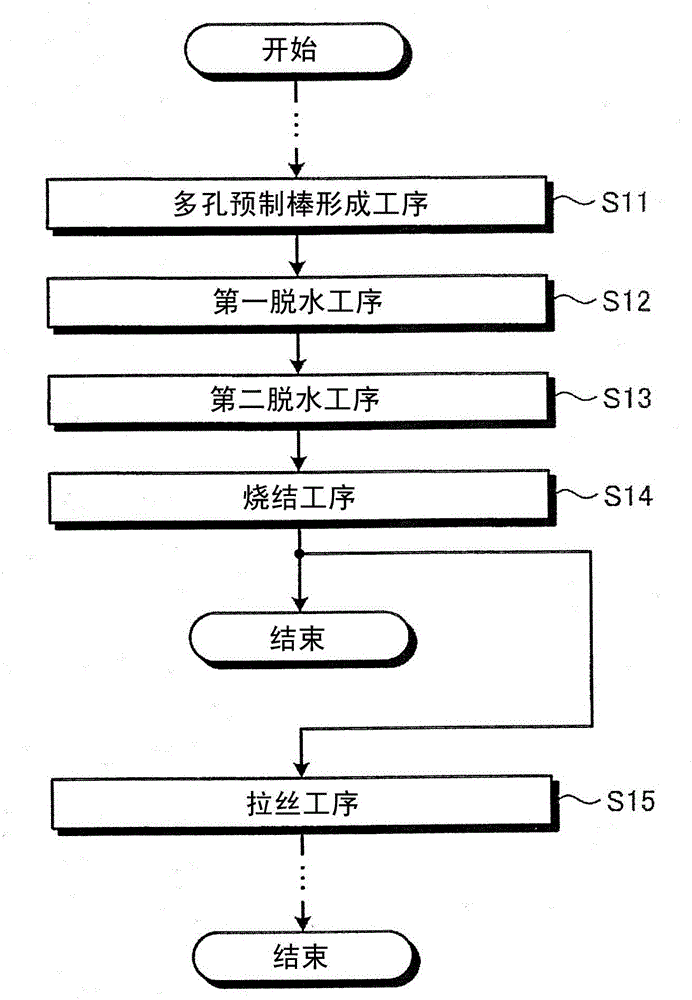
[0028] Here, refer to Figure 1 ~ Figure 4 A method of manufacturing an optical fiber preform and a method of manufacturing an optical fiber according to the first embodiment will be described. figure 1 It is a flowchart showing the procedure of the manufacturing method of the optical fiber preform and the manufacturing method of the optical fiber of the first embodiment. Such as figure 1 As shown, the method for manufacturing an optical fiber preform according to the first embodiment includes a porous preform forming step (step S11), a first dehydration step (step S12), a second dehydration step (step S13), and a sintering step (step S14) . In addition, the optical fiber manufacturing method of the first embodiment further includes a drawing step (step S15 ) after the sintering step (step S14 ) of the optical fiber preform manufacturing method. It should be noted that the method for manufacturing an optical fiber preform and the method for manufacturing an optical fiber ac...

no. 2 approach 〕

[0057] Next, refer to Figure 5 A method of manufacturing an optical fiber preform and a method of manufacturing an optical fiber according to the second embodiment will be described. In addition, in the manufacturing method of the optical fiber preform and the manufacturing method of the optical fiber in 2nd Embodiment, the same apparatus structure as 1st Embodiment is used. Therefore, in the description of the second embodiment, by appropriately referring to Figure 2 ~ Figure 3 The device structure is shown, and the description of the device structure is omitted.

[0058] Figure 5 It is a flowchart showing the procedure of the manufacturing method of the optical fiber preform and the manufacturing method of the optical fiber of the second embodiment. Such as Figure 5 As shown, the method for manufacturing an optical fiber preform according to the second embodiment includes a porous preform forming step (step S21), a first dehydration step (step S22), a second dehydrat...

Embodiment 1

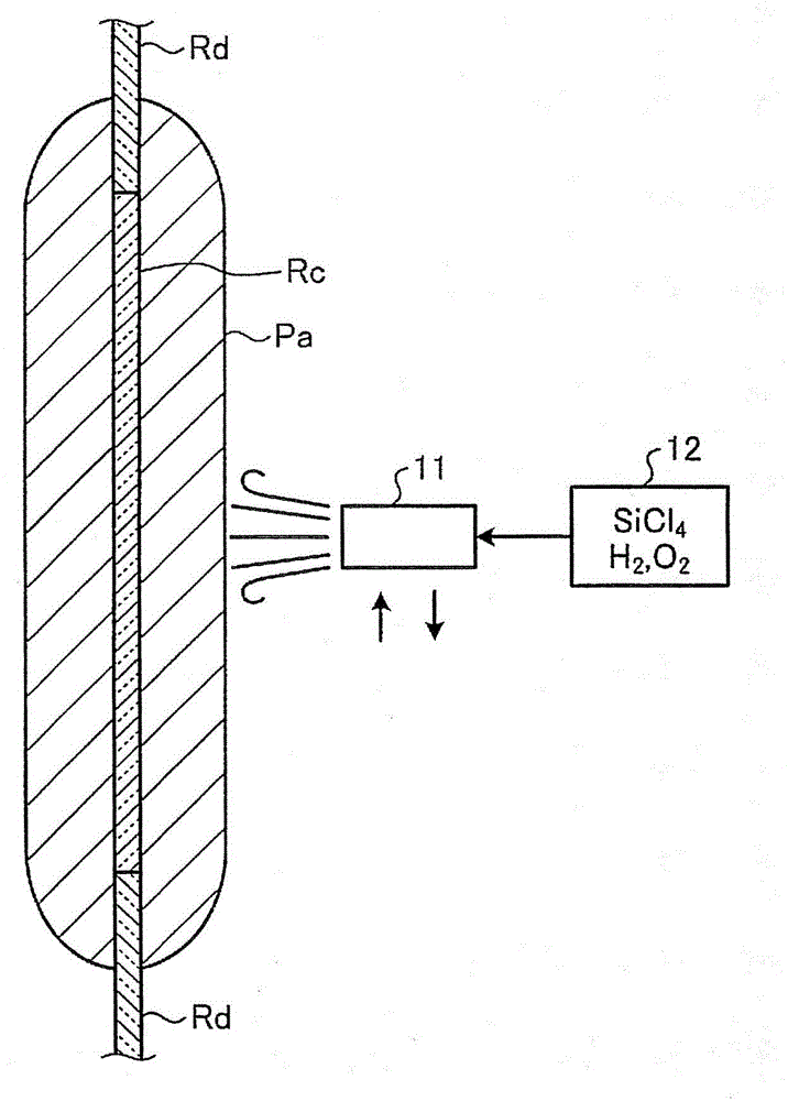
[0078] In the porous preform forming process of Example 1, the core produced by the VAD method was dehydrated and vitrified in a vitrification furnace of a down-draw method generally performed, and then stretched to a predetermined diameter. Mandrel Rc. It should be noted that the cladding diameter / core diameter of the core rod Rc is 4.2, and the packing density around the core rod Rc is 0.7 g / cm by OVD method. 3 The porous layer, thus making the porous preform Pa.

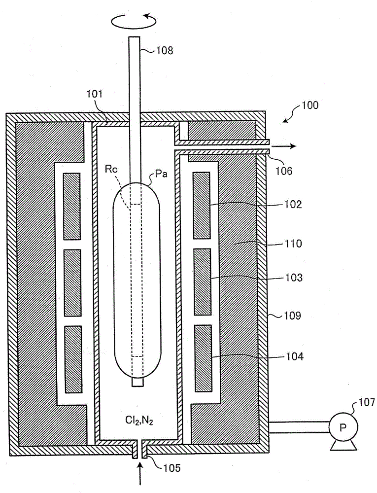
[0079] In the first dehydration process, the second dehydration process and the semi-sintering process, use image 3 Using a vitrification furnace 100 as shown, the porous preform Pa is semi-sintered into an optical fiber preform Pb in a "translucent glass state". At this time, the treatment temperature and treatment time of the first dehydration step were 1000°C×3 hours, and the treatment temperature and treatment time of the second dehydration step were 1200°C×2 hours. In addition, the ambient gas in the furn...


PUM

PropertyMeasurementUnit
densityaaaaaaaaaa
densityaaaaaaaaaa
densityaaaaaaaaaa

Abstract

A method for producing an optical fiber preform comprises: a step for forming a porous preform by depositing fine silica particles on the outer circumference of a target rod; and a vitrification step in which the porous preform is dehydrated and sintered by at least three heat treatment steps. The porous preform is dehydrated in an atmosphere that contains a halogen gas or a halogen-based compound gas in the first heat treatment step, which is a heat treatment step carried out first among the three heat treatment steps, and in the second heat treatment step, which is a heat treatment step carried out secondly among the three heat treatment steps. The treatment temperature in the second heat treatment step is higher than the treatment temperature in the first heat treatment step.

Description

technical field [0001] The invention relates to a method for manufacturing an optical fiber preform and a method for manufacturing an optical fiber. Background technique [0002] In recent years, in order to reduce manufacturing costs, the size of optical fiber preforms has been increasing. In the case of a porous preform used to produce an optical fiber preform, if the bulk density (or also called powder density) is low, the outer diameter of the porous preform becomes thicker, and the heating furnace for heating the porous preform needs to be enlarged. . Therefore, it is necessary to increase the bulk density of the porous preform (for example, refer to Patent Document 1). [0003] In addition, as a technique for reducing manufacturing costs, there is a method of manufacturing an optical fiber preform in which a porous preform is sintered under reduced pressure until it becomes a semi-transparent glass preform layer containing independent cells, and a non-helium atmosphe...

Claims


Application Information

Patent Timeline
Patent Type & Authority Applications(China)
IPC IPC(8): C03B37/014G02B6/00
CPCC03B37/014C03B37/0146B29D11/00721C03B37/01446G02B6/00C03C13/046C03C2213/00
Inventor 菅沼一彦折田伸昭金尾昭博
Owner FURUKAWA ELECTRIC CO LTD
Why Eureka
Try Eureka