Selective plasma melting rapid prototyping equipment and method

A molding equipment and plasma technology, applied in the field of ion casting rapid prototyping equipment, can solve the problems of uneven surface of parts, low laser power, and low mechanical properties of three-dimensional metal parts.

Active Publication Date: 2016-09-07
中研碧诚(北京)科技有限公司
View PDF9 Cites 8 Cited by
  • Summary
  • Abstract
  • Description
  • Claims
  • Application Information

AI Technical Summary

Problems solved by technology

[0012] First, the laser cannot protect the droplet, and it is necessary to pass a protective gas at the wire feeder. The protective gas is easy to cool the droplet, which has an adverse effect on the solidification and layered formation of the droplet, resulting in low mechanical properties of the three-dimensional metal parts.
[0013] Second, the laser power is low and the diameter of the metal wire is large, so it is difficult to realize the rapid prototyping of ceramic and composite material parts
[0014] Third, due to the surface tension, the droplet cooling and solidification will produce circular shrinkage, resulting in the surface of the part is not smooth

Method used


Image

  • Selective plasma melting rapid prototyping equipment and method
  • Selective plasma melting rapid prototyping equipment and method
  • Selective plasma melting rapid prototyping equipment and method

Examples


Embodiment 2

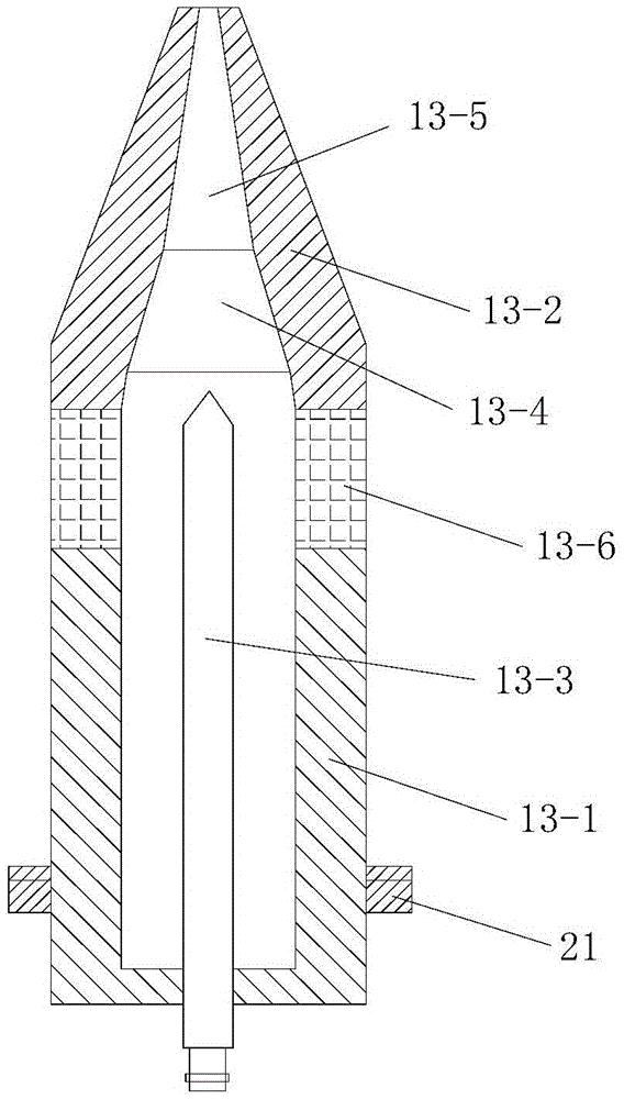
[0205] In this example, if Figure 7 As shown, the difference between the selected area plasma casting rapid prototyping equipment used and the embodiment 1 is that the nozzle 13-5 and the powder circulation channel 14 are arranged coaxially.

[0206] In this way, after changing the direction of the plasma beam through the nozzle 13-5, the thermal load impact of the plasma jet on the anode nozzle 13-2 can be effectively reduced, and the anode ablation condition is improved. At the same time, since the nozzle 13-5 is coaxially arranged with the powder circulation channel 14, the acceleration, heating and melting process of the powder will not be affected, and the use effect is very good.

[0207] In this embodiment, the structure, connection relationship and working principle of the rest of the selected area plasma casting rapid prototyping equipment are the same as those in Embodiment 1.

[0208] In this embodiment, the selected area plasma casting rapid prototyping method ad...


PUM

PropertyMeasurementUnit
diameteraaaaaaaaaa
heightaaaaaaaaaa

Abstract

The invention discloses selective plasma melting rapid prototyping equipment and method. The equipment comprises a monitoring system, a plasma beam processing system, and a level printing table a powder sending and spreading device. The plasma beam processing system includes a plurality of plasma beam processing devices; each plasma beam processing device is composed of a plasma generator, a printing position adjusting device, a gas supply device and a wire sending device; the monitoring system includes a plurality of plasma beam processing monitoring devices; each plasma beam processing monitoring device includes a temperature detection unit, a horizontal movement controller, a distance detecting unit and a printing distance adjusting controller. The method comprises the following steps: 1, acquisition of a 3D model of a workpiece to be molded, and hierarchical slicing processing; 2, scanning path filling; 3, printing path acquisition; and 4, printing layer by layer from top to bottom. The invention has the advantages of reasonable design, simple operation, high molding efficiency, good usage effect, no need of enclosed moulding chamber or the vacuum environment, and no need of protection atmosphere or vacuum environment.

Description

technical field [0001] The invention belongs to the technical field of rapid prototyping, and in particular relates to a rapid prototyping device and method for selective plasma melting and casting. Background technique [0002] At present, the rapid prototyping technology of metal parts at home and abroad is mainly the selective laser melting rapid prototyping technology (Selective laser melting, SLM). For example, the US Patent No. US7047098 "PROCESS ANDDEVICE FOR PRODUCING A SHAPED BODY BY SELECTIVE LASER MELTING" describes in detail a selective laser melting forming method and equipment for manufacturing dense parts using a three-dimensional digital model. The Chinese invention patent with the publication number CN1603031A "A Method and Device for Selective Laser Melting Rapid Prototyping of Metal Parts" discloses a method and device for selective laser melting rapid prototyping of metal parts. The device includes semiconductor pumped YAG laser or fiber laser, beam focu...

Claims


Application Information

Patent Timeline
Patent Type & Authority Applications(China)
IPC IPC(8): B29C67/00B22F3/115B28B1/00B33Y10/00B33Y30/00
CPCB22F3/115B28B1/001
Inventor 华云峰
Owner 中研碧诚(北京)科技有限公司
Why Eureka
Try Eureka