Al technical title is built by PatSnap Al team. It summarizes the technical point description of the patent document.
A technology of controller and servo controller, which is applied in the direction of vibration suppression adjustment, non-rotational vibration suppression, shock absorber, etc., can solve the problems of liquid leakage, easy wear, etc., to reduce pulsation, reduce pressure and flow pulsation and impact, The effect of strong applicability
Active Publication Date: 2016-09-07
YANSHAN UNIV
View PDF6 Cites 8 Cited by
Summary
Abstract
Description
Claims
Application Information
AI Technical Summary
This helps you quickly interpret patents by identifying the three key elements:
Problems solved by technology
Method used
Benefits of technology
Problems solved by technology
[0005] Ordinary magneto-rheological pulsation controllers use the gap between the working cylinder and the piston as a damping channel. During the reciprocating motion of the controller, it is easy to cause the phenomenon that the piston rod and the working cylinder are not on the same axis, and the piston rod is inclined relative to the cylinder. The piston rod sealing ring is deformed by unilateral pressure and is easy to wear and cause liquid leakage
Method used
Image
Click on the blue label to locate the original text in one second.
Reading with bidirectional positioning of images and text.
Examples
Embodiment Construction
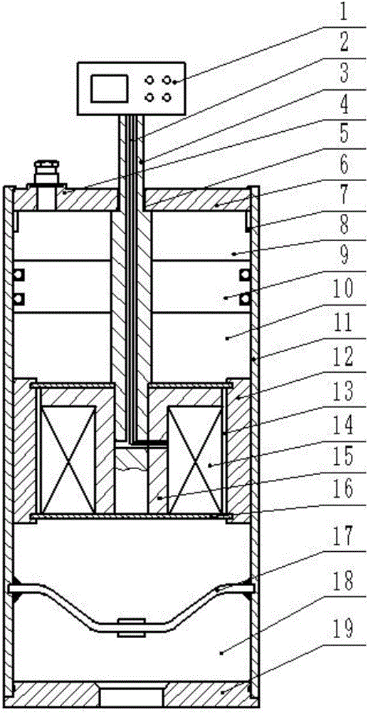
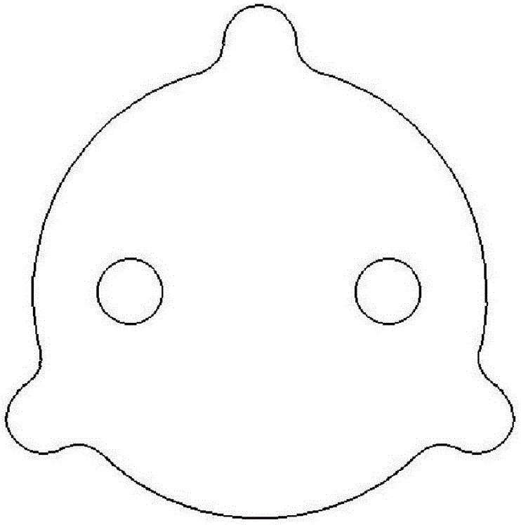
[0020] exist figure 1 and figure 2 In the schematic diagram of the present invention shown, the working cylinder 11 is a hollow cylinder with upper and lower openings, a lower end cover 19 is provided at the lower end of the working cylinder, and a through hole is provided in the middle of the lower end cover for connecting hydraulic pipelines. . In the working cylinder, the upper part of the lower end cover is fixedly connected with a liquid separation diaphragm 17, and there is a hydraulic oil chamber 18 between the liquid separation diaphragm and the lower end cover. The upper end of the working cylinder is fixedly connected with the upper end cover 6, and the upper end cover is provided with a threaded hole, and the bottom of the charging valve 4 is sleeved with the sealing ring 5, and is threaded with the upper end cover through the threaded hole. The limit sleeve 7 is fixedly connected to the bottom of the upper end cover. A through hole is provided in the middle of ...
PUM
Abstract
An electromechanical integrated pulsator controller mainly comprises a working cylinder, a lower end cover, a liquid separating membrane, a fluid chamber, an upper end cover, an inflation valve, a seal ring, limit sleeves, a piston rod, a servo controller, a floating piston, a compensating air chamber, a magnetorheological fluid, an iron core, solenoid coils, gaskets, an outer piston sleeve, a damping channel and a wire. The internal structure of the electromechanical integrated pulsator controller is simple, and an accurate damping force can be obtained as required, so that pulsations are reduced, and the effect of semi-active control is achieved. High frequency pulsations and variable frequency pulsations of a hydraulic pipeline of an airplane can be absorbed. The damping effect is more remarkable. The electromechanical integrated pulsator controller is simple and convenient to use, compact in structure, and high in practicability. A user can load a control program as required. Hydraulic impacts and pulsations can be absorbed quickly and efficiently. The electromechanical integrated pulsator controller has high practicability, can be mounted on the hydraulic pipeline on the airplane, and is used for reducing the pressure and the flow pulsations and impacts in the hydraulic pipeline.
Description
technical field [0001] The invention belongs to the technical field of electromechanical integration vibration control, and in particular relates to a pulsation controller. Background technique [0002] Most modern aircraft hydraulic systems use variable displacement plunger pumps. One of the inherent characteristics of the pumps is the pulsating flow output, which will generate pressure pulsations. The source of vibration is mainly the rotary motion of the hydraulic pump, the reciprocating suction and discharge process, and the resonance in the pipeline. The vibration of the system is divided into two basic types: mechanical vibration and fluid vibration. At present, the shock absorbers of aircraft hydraulic pipelines are mostly used to reduce mechanical vibration, but the pressure pulsation generated by the pipelines cannot be well controlled, which not only affects the working performance and life of the hydraulic system, but also endangers the lives of passengers and af...
Claims
Application Information
Patent Timeline
Application Date:The date an application was filed.
Publication Date:The date a patent or application was officially published.
First Publication Date:The earliest publication date of a patent with the same application number.
Issue Date:Publication date of the patent grant document.
PCT Entry Date:The Entry date of PCT National Phase.
Estimated Expiry Date:The statutory expiry date of a patent right according to the Patent Law, and it is the longest term of protection that the patent right can achieve without the termination of the patent right due to other reasons(Term extension factor has been taken into account ).
Invalid Date:Actual expiry date is based on effective date or publication date of legal transaction data of invalid patent.