
Eureka
For R&D, Eureka makes reading and utilizing patents & technical documents easy.
Eureka AIR
Designed for self-driven R&D workflows. Generate viable solutions, solve complex R&D challenges, empower your innovation with AI.

Eureka Materials
Designed for material experts only. Revolutionize your material R&D, from search, analyze, to developing new materials.

TechResearch
Generate reliable direction feasibility study reports for your R&D in just a few steps.

TechSeek
Discover and master advanced knowledge NOW. Basics, ideas, possibilities, all at once.

TechMind
As an expert in R&D Theories, TechMind can generates customized viable solutions instantly.

TechRisk
Analyze your overall solution with one click, know your potential R&D risks in advance.

TechMonitor
Get weekly tech updates, stay abreast of the latest tech innovations and key insights.
Oil-immersed power transformer
A voltage transformer and oil-immersed technology, applied in transformer/inductor casing, transformer/inductor cooling, transformer/inductor magnetic core, etc., can solve the problems of less materials, unsuitable transformers, high cost of liquid metal, etc.
- Summary
- Abstract
- Description
- Claims
- Application Information
AI Technical Summary
Problems solved by technology
Method used
Image

Examples
Embodiment 1
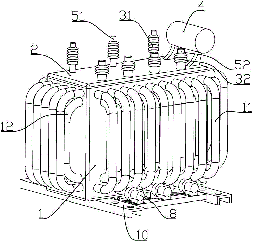
[0064] according to Figure 1 to Figure 8 As shown, this embodiment is an oil-immersed electric voltage transformer, which includes a box body 1 with an open upper end, a cover body 2 fixedly and sealingly connected to the upper end of the box body, an iron core 6 fixedly installed at the bottom of the box body, and a fixedly installed Winding assembly 5 on iron core.
[0065] The iron core includes three longitudinally arranged core columns and horizontal iron yokes connected to the upper and lower ends of each core column; the lower part of the iron core at the lower end of the iron core is connected with a base 61, and the base is connected to the box body. Bottom connection.
[0066] The winding assembly includes a ceramic base 50 and three sets of high-voltage winding coils 55 and three sets of low-voltage winding coils 56 integrally formed in the ceramic base. The coil is formed on the outer periphery of the port, and the high-voltage winding coil is located on the out...
Embodiment 2
[0086] In this embodiment, on the basis of Embodiment 1, the oil pump is further improved, specifically: combining Figure 9 to Figure 16 As shown, the oil pump 8 includes a centrifugal pump housing 82, an impeller 85 installed in the centrifugal pump housing, a piston pump housing 83 fixedly connected to one end of the centrifugal pump housing, and a piston member 88 slidingly installed in the piston pump housing. , and a motor 81 fixedly connected to the other end of the centrifugal pump casing for driving the impeller and the piston.
[0087] The motor is connected with a connecting frame 812, and the outer wall of the centrifugal pump casing is integrally formed with a connecting head 822, and the connecting head and the connecting frame are connected by screws; the side wall of the centrifugal pump casing is formed with a liquid outlet 821.
[0088] A drive turntable 811 is connected to the output shaft of the motor. The drive turntable is close to but not in contact wit...
Embodiment 3
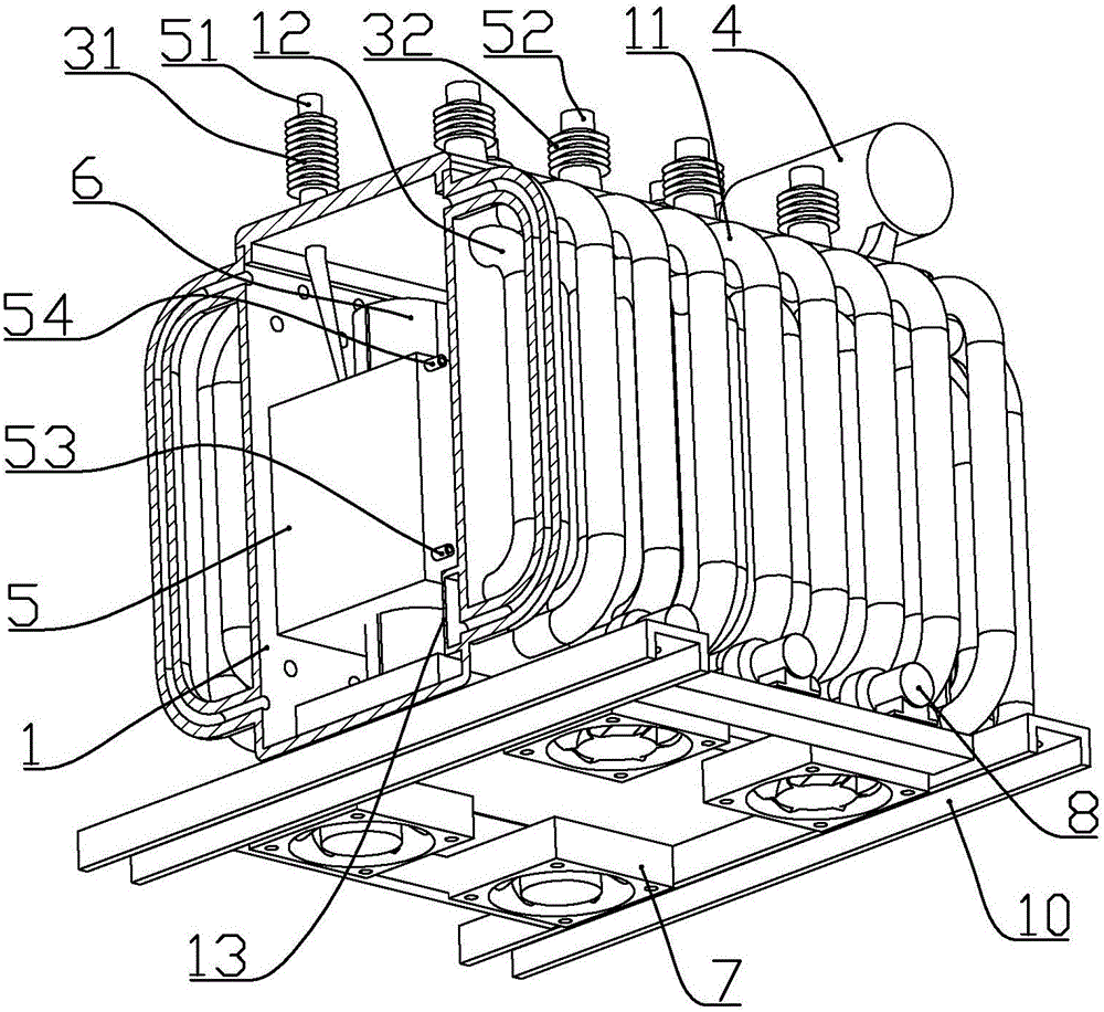
[0104] according to figure 1 , figure 2 , Figure 9 to Figure 16 As shown, this embodiment is an oil-immersed electric voltage transformer, which includes a box body 1 with an open upper end, a cover body 2 fixedly and sealingly connected to the upper end of the box body, an iron core 6 fixedly installed at the bottom of the box body, and a fixedly installed Winding assembly 5 on iron core.
[0105] The iron core includes three longitudinally arranged core columns and horizontal iron yokes connected to the upper and lower ends of each core column; the lower part of the iron core at the lower end of the iron core is connected with a base 61, and the base is connected to the box body. Bottom connection.
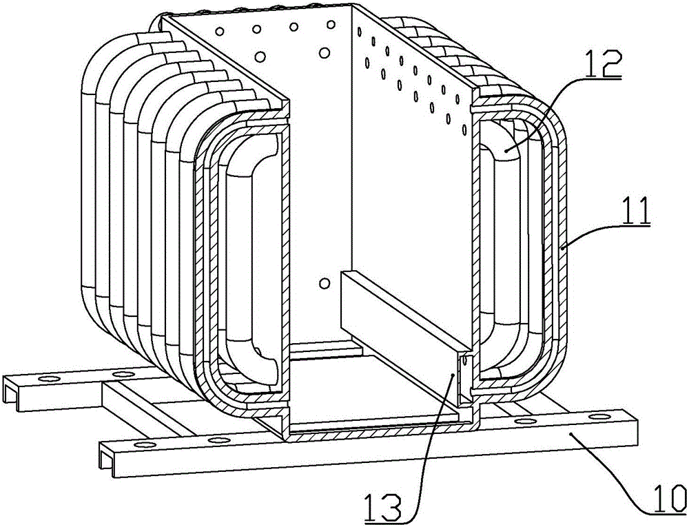
[0106]The bottom of the box body is fixedly connected with a bracket 10 arranged horizontally, and the side of the box body is connected with a plurality of heat dissipation inner tubes 12 which are arranged vertically and are U-shaped as a whole. The outer side is also co...
PUM
 Abstract
Description
Claims
Application Information
 - R&D Engineer
- R&D Manager
- IP Professional
- Industry Leading Data Capabilities
- Powerful AI technology
- Patent DNA Extraction
Browse by: Latest US Patents, China's latest patents, Technical Efficacy Thesaurus, Application Domain, Technology Topic, Popular Technical Reports.
© 2024 PatSnap. All rights reserved.Legal|Privacy policy|Modern Slavery Act Transparency Statement|Sitemap|About US| Contact US: help@patsnap.com