Pipe welding method

A welding method and pipeline technology, applied in welding equipment, tubular objects, arc welding equipment, etc., can solve the problems of restricting pipeline construction efficiency and low welding efficiency, and achieve controllable deposition efficiency, excellent weld performance, and low dilution rate low effect

Inactive Publication Date: 2016-09-28
CHENGDU FANXINJIA TECH
View PDF5 Cites 3 Cited by
  • Summary
  • Abstract
  • Description
  • Claims
  • Application Information

AI Technical Summary

Problems solved by technology

Its main disadvantage is low welding efficiency. Pipe welding is generally suitable for root welding of small-diameter pipes. The conventional manual argon tungsten arc welding method has restricted the construction efficiency of pipes.

Method used


Image

  • Pipe welding method

Examples


Embodiment Construction

[0033] The present invention will be described in further detail below through specific implementation examples and in conjunction with the accompanying drawings.

[0034] A pipeline welding method is characterized in that, comprising the following steps:

[0035] S1: Clean the pipes to be welded to remove oil and other impurities on the surface of the pipes.

[0036] S2: Preheat the pipeline to be welded, and the method of preheating before welding can effectively prevent delayed cracking caused by hydrogen.

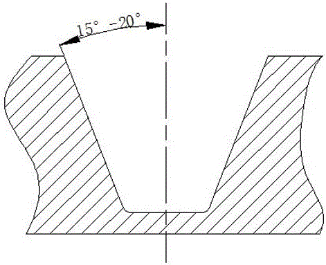
[0037] S3: Perform U-shaped groove treatment on the welded part of the pipe.

[0038] S4: For the pipe after U-shaped groove treatment, use the internal counterpart with argon filling protection function to assemble the pipe.

[0039] S5: anti-oxidation treatment.

[0040] S6: Weld the pipeline with hot wire TIG automatic welding equipment.

[0041] S7: Perform heat treatment on the welded pipe.

[0042] Further, the step S3 includes the following sub-steps:

[00...


PUM


Abstract

The invention discloses a pipe welding method. The pipe welding method comprises the following steps: (S1) a pipe to be welded is cleaned; (S2) the pipe to be welded is preheated; (S3) the U-shaped groove treatment is performed for the welded place of the pipe; (S4) the pipe is assembled by an inner aligner with an inner argon charging protection function after the U-shaped groove treatment; (S5) the oxidation resisting treatment is performed; (S6) the pipe is welded through hot wire TIG automatic welding equipment; and (S7) the welded pipe is heated.

Description

technical field [0001] The invention relates to the technical field of pipeline welding, in particular to a pipeline welding method. Background technique [0002] In recent years, the exploitation of conventional gas reservoirs at home and abroad has been gradually saturated. In order to meet market demand, natural gas exploitation has gradually moved towards unconventional gas fields such as high temperature and high acidity. South Yolotan gas field in Turkmenistan belongs to the "six high" gas fields with high temperature, high pressure, high yield, high content of hydrogen sulfide, high content of carbon dioxide, and high content of chloride ions. Cracking and other mechanisms of cracking corrosion. In view of the working conditions of high operating pressure and harsh medium corrosion, due to the high strength and good plasticity of the nickel-based alloy, it can resist stress corrosion and acid corrosion, especially for high-concentration chloride media, and its corros...

Claims


Application Information

Patent Timeline
Patent Type & Authority Applications(China)
IPC IPC(8): B23K9/235B23K9/167
CPCB23K9/235B23K9/167B23K2101/06
Inventor 高静
Owner CHENGDU FANXINJIA TECH
Why Eureka
Try Eureka