
Direct electrogenesis method and device for sewage treatment

A technology for sewage treatment and electric device, applied in the field of water treatment, can solve the problems of poor application effect, high investment cost, complicated operation control, etc., and achieve the effect of good treatment effect, good treatment effect and lower device cost.

Inactive Publication Date: 2016-10-05
李泽唐
View PDF0 Cites 4 Cited by
  • Summary
  • Abstract
  • Description
  • Claims
  • Application Information

AI Technical Summary

Problems solved by technology

Due to the complex operation control and huge investment cost of sludge anaerobic generation biogas power plant, the current application effect in China is not good

Method used


Image

  • Direct electrogenesis method and device for sewage treatment
  • Direct electrogenesis method and device for sewage treatment
  • Direct electrogenesis method and device for sewage treatment

Examples


specific Embodiment 1

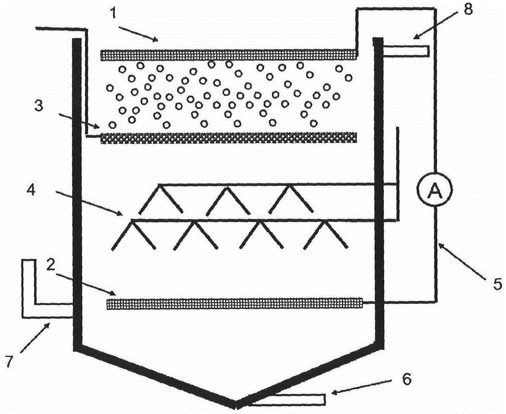
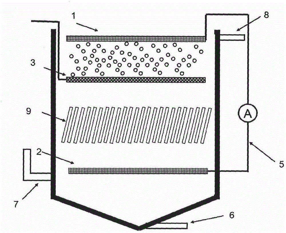
[0023] The microbial redox power generation reactor for sewage treatment proposed by the present invention is a gravity upflow type, and its structure is as follows: figure 2 As shown, the bottom of the structure is for sludge collection and has a sludge discharge port 6, and the reduction anode 2 is close to the bottom of the reaction tank, above which there is a gas-liquid separator 4 for sludge anaerobic fermentation to generate gas, to collect biogas resources generated by anaerobic sludge At the same time, prevent the reducing gas from floating to the top of the pool to affect the oxidation potential of the aeration area. The air cathode 1 is located on the water surface of the pool top, and the shallow aeration device 3 is located at 80 cm below the water. The electrons produced by the sludge microorganisms are transmitted to the air cathode through the external circuit connected by the wire between the anode and the cathode to generate current. The raw water enters from...

specific Embodiment 2

[0027] The microbial redox power generation device for sewage treatment proposed by the present invention is a horizontal plug-flow type, and its structure is as follows: Figure 5 As shown, the bottom of the structure is for sludge collection with a sludge outlet 6, the reduction anode 2 is close to the bottom of the reaction tank, the air cathode 1 is located on the water surface on the top of the tank, and the plug-flow surface aerator 11 is installed near the water inlet, and the raw water passes through the inlet. The water inlet 7 enters from the lower part, and the incoming water flows up through the retaining wall 12 to the vicinity of the surface aerator, and during the ascent process, the sediment and large-grained sludge are separated to the bottom sludge outlet 6, and the sewage is transferred to the surface aerator The aeration also plays the role of pushing flow, the cathode in the electrode module is plate-shaped, and the anode is cylindrical. The cathode electr...


PUM

PropertyMeasurementUnit
thicknessaaaaaaaaaa
surface areaaaaaaaaaaa

Abstract

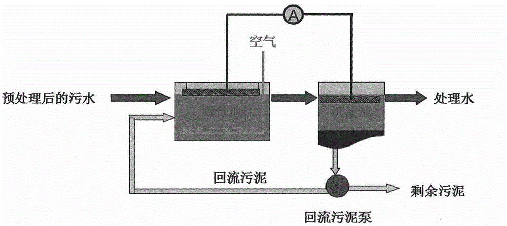
The invention provides a direct electrogenesis method and device for sewage treatment. The method is characterized in that an oxygen-rich area is formed in the upper part of a sewage treatment building or in an aeration tank through blast aeration and mechanical aeration and has a positive redox potential, and an anoxic zone is formed in the bottom of a building or in a settling pond and has a negative redox potential. An electrode has a modular structure, conducting layers are respectively arranged in the oxygen-rich area and the anoxic zone and are used for collecting power produced by microbe redox and redox potential difference is potential. The device comprises a vertical upflow shallow aeration sewage generating unit, a horizontal plug-flow surface layer mechanical aeration generating unit or a redox potential generating unit between an aeration tank and a settling pond. The method and device promote a redox reaction and realizes sewage electric energy collection. The device can be used as a sensor for real-time monitoring of an aeration degree, improves nitrogen and phosphorus removal effects and can be used as a capacitor for improving water heavy metal ion electro-adsorption removal.

Description

technical field [0001] The invention relates to a power generation technology combined with sewage treatment technology, in particular to a device for generating electricity and collecting sewage during sewage treatment operation, and belongs to the technical field of water treatment. Background technique [0002] With the rapid development of my country's urbanization process, sewage treatment plants are being built in a large area of ​​my country, and the sewage treatment rate is gradually increasing. However, the existing sewage treatment process will consume a lot of external energy and resources; at the same time, sewage is an important renewable Resources should be converted into energy consumption as the energy or resource recovery generated in the process of sewage treatment. There are currently few ways to directly extract energy from sewage. One of the main ways of utilization is to produce biodiesel based on the cultivation of algae in sewage, which requires a lot...

Claims


Application Information

Patent Timeline
Patent Type & Authority Applications(China)
IPC IPC(8): C02F3/30H01M8/16
CPCY02E60/50
Inventor 李泽唐
Owner 李泽唐
Learn More