Gas supply system and hydrogen station

A gas supply and gas technology, applied in the field of gas supply system and hydrogen refueling station, can solve the problems of enlarging the setting area of ​​the first support platform, enlarging the hydrogen compression device, enlarging the hydrogen refueling station, etc.

Active Publication Date: 2016-10-12
KOBE STEEL LTD
View PDF8 Cites 13 Cited by
  • Summary
  • Abstract
  • Description
  • Claims
  • Application Information

AI Technical Summary

Problems solved by technology

As a result, the size of the hydrogen compression device will increase
In addition, since the hydrogen compression device and accumulator unit are installed independently, the overall size of the hydrogen refueling station will increase
In Patent Document 2, the compressor, the first accumulator, the heat exchanger, and the distributor are arranged on the first support table, so the installation area of ​​the first support table becomes large.

Method used


Image

  • Gas supply system and hydrogen station
  • Gas supply system and hydrogen station
  • Gas supply system and hydrogen station

Examples


no. 1 approach

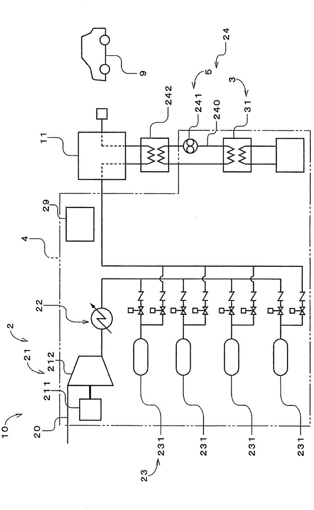
[0029] figure 1 It is a figure which shows the hydrogen refueling station 10 which concerns on 1st Embodiment of this invention. The hydrogen refueling station 10 includes a gas supply system 2 and a distributor 11 as a filling device. The gas supply system 2 supplies hydrogen gas to the distributor 11 . The dispenser 11 fills the vehicle 9 as a tank-mounted device with hydrogen gas. Vehicle 9 is, for example, a fuel cell vehicle. The gas supply system 2 includes a gas flow path 20 , a compressor assembly 21 , a gas cooling unit 22 , an accumulator assembly 23 , a precooling system 24 , a casing 4 and a control unit 29 indicated by dashed-two dotted lines. The compressor assembly 21 , a part of the gas cooling unit 22 , and the accumulator assembly 23 are arranged on the gas flow path 20 . Hydrogen gas flows toward the distributor 11 in the gas flow path 20 . The controller 29 controls the compressor assembly 21 , the accumulator assembly 23 and the precooling system 24 ....

Embodiment approach

[0058] As mentioned above, although the 1st Embodiment of this invention was described, this invention is not limited to the said 1st Embodiment, Various changes are possible.

[0059] exist Figure 9 In the hydrogen refueling station 10 a shown, the pre-cooling heat exchanger 242 can also be arranged in the casing 4 . In addition, in figure 1In the gas supply system 2 shown, the pre-cooling heat exchanger 242 may also be arranged in the cabinet 4 . At this time, all the equipment of the compressor assembly 21 , the gas cooling unit 22 , the accumulator assembly 23 , and the precooling system 24 are arranged inside the cabinet 4 or the upper part 42 of the cabinet 4 . A cover for covering the heat exhaust unit 223 and the condensation unit 33 may be attached to the upper part 42 and all the devices may be arranged in the cabinet 4 .

[0060] The gas cooler 222 may be a plate heat exchanger other than a microchannel heat exchanger as long as it is directly fixed to the compr...

no. 2 approach

[0077] The gas supply system 2 according to the second embodiment of the present invention will be described. Here, only configurations different from those of the first embodiment will be described, and descriptions of configurations that are the same as those of the first embodiment will be omitted. in addition, Figure 1 to Figure 6 It is also used as a diagram showing the gas supply system according to the second embodiment.

[0078] Figure 10 is a side view of the gas supply system 2 . Figure 11 From Figure 10 The left side view of the diagram of the gas supply system 2. exist Figure 10 and Figure 11 In , the casing 4 is represented by a two-dot dash line. In addition, only the main equipment of the gas supply system 2 is shown, and the illustration of peripheral components such as piping is omitted. exist Figure 10 and Figure 11 in, will figure 1 The brine pump 241 of the precooling system 2 shown, the evaporator 31 of the refrigerator 3, Figure 6 The...


PUM


Abstract

The gas supply system (2) is provided with a compressor unit (21), pressure accumulator units (23), a pre-cooling system (24), and a housing (4). In the gas supply system (2), the compressor unit (21) is disposed inside the housing (4) oriented in the vertical direction and the pre-cooling system (24) is disposed above the pressure accumulator units (23). The compressor unit (21) and the pressure accumulator units (23) are covered by a single rectangular parallelepiped-shaped housing (4).

Description

technical field [0001] The invention relates to a gas supply system and a hydrogenation station. Background technique [0002] Patent Document 1 discloses a hydrogen compression device used in a hydrogen refueling station. The hydrogen compressing device is provided with a hydrogen compressing device main body, a compressor driving motor, a gas cooler, and the like on a common base. Hydrogen gas boosted to a predetermined pressure in stages by the hydrogen compressor is temporarily stored in the accumulator unit. To supply the boosted hydrogen gas to the fuel cell vehicle, a distributor equipped with an adapter suitable for a supply port of the fuel cell vehicle is connected to the accumulator assembly. [0003] The hydrogen refueling station disclosed in Patent Document 2 has a first support platform, a compressor, a first accumulator, a distributor, a heat exchanger for cooling hydrogen gas supplied to the distributor, and a branch line for connecting a first expansion u...

Claims


Application Information

Patent Timeline
Patent Type & Authority Applications(China)
IPC IPC(8): F17C7/00
CPCY02E70/30F04B41/02F17C5/06F17C2205/0111F17C2205/0142F17C2221/012F17C2223/0123F17C2223/033F17C2225/0123F17C2225/036F17C2227/0164F17C2227/0348F17C2227/0355F17C2227/0388F17C2227/041F17C2250/043F17C2250/0452F17C2250/072F17C2250/075F17C2265/065F17C2270/0139Y02P90/45B60K15/07F17C2205/0376F17C2227/0157F17C2227/0344F17C2260/018F17C2260/038F17C2260/042F17C2265/061F17C2265/063F17C5/007Y02E60/32B60S5/02F17C7/00F17C13/002F17C2227/0128F17C2227/0353
Inventor 名仓见治垣内哲也大久野孝史野一色公二藤泽彰利三浦真一
Owner KOBE STEEL LTD
Why Eureka
Try Eureka