Nondestructive testing method of residual stress of thermally grown oxide layers in thermal barrier coatings

An oxide layer, non-destructive testing technology, used in force/torque/work measuring instruments, measuring devices, material excitation analysis, etc. The effect of strong penetration

Inactive Publication Date: 2016-11-02
SHANGHAI INST OF CERAMIC CHEM & TECH CHINESE ACAD OF SCI
View PDF5 Cites 19 Cited by
  • Summary
  • Abstract
  • Description
  • Claims
  • Application Information

AI Technical Summary

Problems solved by technology

[0008] In order to overcome the deficiencies of the above-mentioned existing stress detection technology, the technical problem to be solved by the present invention is to provide a non-destructive detection method for the residual stress of the thermally grown oxide layer in the thermal barrier coating, which can successfully solve the stress detection of other coatings. The means cannot measure the lack of stress distribution in the TGO layer without destroying the tested sample
[0010] According to the present invention, ① can pass Cr 3+ The distribution of internal stress in the TGO layer is obtained by fluorescence compression spectroscopy, which solves the technical problem that the traditional stress detection method is difficult to measure the stress of the TGO layer; The change of internal stress of the TGO layer before and after the assessment under various working conditions (such as thermal shock, constant temperature oxidation, thermal cycle or high temperature flame thermal shock, etc.) provides an experimental basis for the research on the service behavior and failure mechanism of the coating; ③ for the actual The non-destructive testing of TGO internal stress in the coating before and after the service of the workpiece provides the feasibility

Method used


Image

  • Nondestructive testing method of residual stress of thermally grown oxide layers in thermal barrier coatings
  • Nondestructive testing method of residual stress of thermally grown oxide layers in thermal barrier coatings
  • Nondestructive testing method of residual stress of thermally grown oxide layers in thermal barrier coatings

Examples


Embodiment 1

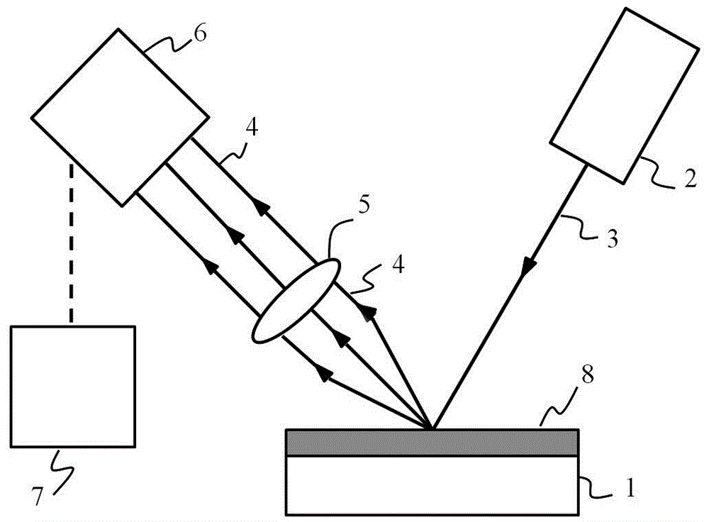
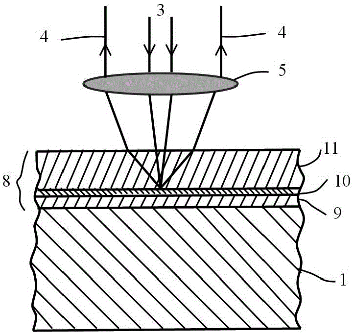
[0056] Using Cr 3+ Measurement of α-Al formed on the surface of the metal bonding layer after special processes (vacuum diffusion treatment, stress relief heat treatment, pre-oxidation treatment or oxidation after high-temperature service, etc.) by fluorescence piezometry 2 o 3 Stress distribution in the layer. Including the following steps:

[0057] Step (1) pretreating, for example, GH3128 nickel-based superalloy, including: roughening and purifying the surface of the metal substrate to be sprayed;

[0058] The size of the superalloy can be Φ30mm×5.8mm. It is sprayed with 20# white corundum sand at a working pressure of 0.4-0.5MPa, followed by ultrasonic cleaning with ethanol for 5 minutes, and then blown dry with compressed air.

[0059] Step (2) Depositing a CoNiCrAlY metal bonding layer on the surface of the treated metal substrate by using a low-pressure plasma spraying (LPPS) process, the thickness of which is 80-100 μm. In addition to the above-mentioned low-pressu...

Embodiment 2

[0068] Using Cr 3+ Fluorescence piezospectroscopy was used to detect the stress change of TGO layer of YSZ coating prepared by PS-PVD process before and after thermal shock. Including the following steps.

[0069] Step (1) pretreating the nickel-based superalloy includes: roughening and purifying the surface of the metal substrate to be sprayed.

[0070] For example, the size of the GH3128 nickel-based superalloy can be 25mm×25mm×2.7mm. First, it is sandblasted with 20# white corundum sand, and the working pressure is 0.4-0.5MPa, followed by ethanol ultrasonic cleaning for 5 minutes, and then compressed air. blow dry.

[0071]Step (2) Depositing a CoNiCrAlY metal bonding layer on the surface of the treated metal substrate by using LPPS process, the thickness of which is 80-100 μm. In addition to the LPPS process, VPS, HVOF and other processes can also be used.

[0072] Step (3) Before spraying the ceramic layer on the surface of the metal bonding layer, in order to obtain ...


PUM

PropertyMeasurementUnit
thicknessaaaaaaaaaa
thicknessaaaaaaaaaa
thicknessaaaaaaaaaa

Abstract

The invention provides a nondestructive testing method of residual stress of thermally grown oxide layers in thermal barrier coatings. The method comprises the following steps: a laser beam with a specific wavelength enters to the surface of a thermally grown oxide layer to be tested, and a fluorescence spectrum of a trace element Cr3+ in the thermally grown oxide layer of the thermal barrier coating is excited; a characteristic peak of the fluorescence spectrum of excited Cr3+ and a characteristic peak of a fluorescence spectrum of Cr3+ excited in a stress-free state are compared, and distribution of internal stress in the thermally grown oxide layer is calculated according to offset of the characteristic peak. The method can solve the technical problem that traditional stress detection methods are difficult to realize stress measurement of TGO (thermally grown oxide) layers; changes of internal stress of TGO layers before and after examinations in various conditions (such as thermal shock, constant temperature oxidation, heat cycle or high temperature plume flow thermal shock, etc.) of a coating sample can be detected without destroy of the sample itself, and experiment foundation is provided for researching service behaviors and failure mechanisms of coatings; feasibility of nondestructive test of TGO internal stress in the coating of a practical workpiece before and after service is provided.

Description

technical field [0001] The present invention relates to a non-destructive detection method for the residual stress of a thermally grown oxide layer in a thermal barrier coating, and more particularly, to a thermal barrier coating prepared by a plasma spraying-physical vapor deposition (PS-PVD) process Method for non-destructive testing of residual stress in thermally grown oxide (TGO) layers. Background technique [0002] Thermal barrier coatings (TBCs) are one of the three key technologies of engine blade technology. To promote the development of advanced engines, it is particularly important to obtain thermal barrier coatings with excellent high-temperature service performance, high reliability, and long life. At present, the common preparation technology of thermal barrier coating mainly adopts plasma spraying (PS) and electron beam-physical vapor deposition (EB-PVD). Plasma sprayed thermal barrier coating is composed of molten and semi-molten droplets deposited, spread ...

Claims


Application Information

Patent Timeline
Patent Type & Authority Applications(China)
IPC IPC(8): G01N21/64G01L5/00
CPCG01L5/0047G01N21/64G01N21/6402G01N21/643G01N2021/6417
Inventor 陶顺衍杨加胜赵华玉邵芳钟兴华王亮
Owner SHANGHAI INST OF CERAMIC CHEM & TECH CHINESE ACAD OF SCI
Why Eureka
Try Eureka