Composite energy comprehensive utilization system of high-rise building and control method thereof

A high-rise building, composite technology, applied in the field of comprehensive energy utilization system, can solve the problem of not considering the domestic hot water and heating supply of high-rise buildings, not considering the energy recovery and utilization of rainwater and domestic sewage, and not considering winter, summer and spring and autumn. Seasonal differences and other problems, to achieve the effect of solving the discontinuous power generation, improving the less power generation, and improving the energy recovery and utilization rate

Inactive Publication Date: 2016-11-09
JIANGSU UNIV
View PDF9 Cites 8 Cited by
  • Summary
  • Abstract
  • Description
  • Claims
  • Application Information

AI Technical Summary

Problems solved by technology

[0004] Chinese Patent Publication No. CN101846396A, titled "High-rise Building Solar Energy and Wind Energy Heating Device", discloses a device including a wind turbine, a water storage tank, a heat collector, an electric heating wire, a controller, etc., the device The problem of hot water supply is solved, but the mechanical energy of rainwater and domestic sewage on the roof of high-rise buildings is not used, and the seasonal differences between winter, summer and spring and autumn are not considered when the system is running.
Chinese Patent Publication No. CN103471166A, titled "A Water Supply and Air-Conditioning Energy-Saving System for High-Rise Building Solar Energy Comprehensive Utilization", discloses a system that includes a solar-wind-powered hot water power generation system, a segmented pump water shaft system, and an air-conditioning cooling fan system. The systems such as the pipeline system and the control panel realize the energy saving of high-rise buildings through the comprehensive utilization of various green energies, but this system also does not c

Method used


Image

  • Composite energy comprehensive utilization system of high-rise building and control method thereof

Examples


Example Embodiment

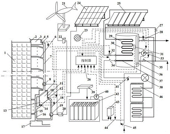
[0021] Such as figure 1 In the composite energy utilization system of the high-rise building shown, a rainwater storage box 3 is fixed on the top of the high-rise building 1, and the top inlet of the rainwater storage box 3 is about 30 cm higher than the top of the high-rise building 1. A filter screen 2 is installed above the rainwater storage tank 3, and rainwater collected on the roof enters the rainwater storage tank 3 through the filter screen 2. A first liquid level sensor 4 is installed on the inner wall of the rainwater storage tank 3, and the bottom water outlet of the rainwater storage tank 3 is connected to the top of the first sewage pipe 7 via a first controllable valve 5. The bottom end of the first sewage pipe 7 is connected to the inlet of the first generator 8, and the outlet of the first generator 8 is connected to the top inlet of the water collection tank 10 through a pipe. The water collection tank 10 is installed at a distance of 5-7m from the ground, und...


PUM


Abstract

The invention discloses a composite energy comprehensive utilization system of a high-rise building and a control method thereof. A rainwater storage tank, a wind turbine generator, a solar cell battery, a solar energy heat collection plate and a hot water tank are arranged on the roof of the high-rise building; rainwater and sewage power generation adopts a two-stage power generation mode and a water tank type power generation mode, the problem of discontinuous power generation of the system is effectively solved, and the energy recovery utilization rate of the high-rise building is improved; a water tank can achieve domestic sewage disposal, the jamming rate and failure rate of rainwater and sewage power generation are effectively lowered, wind energy, solar energy, rainwater and domestic sewage mechanical energy are efficiently and comprehensively utilized, stable power is provided for the high-rise building, and continuous heating and domestic hot water can also be provided for the high-rise building. The operation control mode in winter, summer, spring and autumn is adopted, so that all-weather heating is ensured; and various controllable valves and controllable switches are used for controlling the system, the structure is simple, operation is reliable, and transformation of an existing high-rise building is facilitated.

Description

technical field [0001] The invention belongs to the technical field of high-rise building energy-saving, environment-friendly power generation and water heating cycle supply, and in particular relates to a high-rise building energy comprehensive utilization system. Background technique [0002] High-rise buildings consume a large amount of petrochemical resources such as electricity, coal, and natural gas that produce greenhouse effects in terms of ventilation, lighting, heating, and cooling. Effects and other issues, especially in public high-rise buildings and commercial high-rise buildings built in recent years are fully sealed with central air-conditioning, no window structure, therefore, how to fully recycle, control the energy consumption of high-rise buildings, and improve the use of green energy in high-rise buildings It has become one of the problems urgently needed to be improved and solved in current high-rise buildings. [0003] Whether it is a commercial, publi...

Claims


Application Information

Patent Timeline
IPC IPC(8): F24D15/00F24D19/10E03B1/04E03B3/02E03B7/07H02S10/12H02S40/44
CPCE03B1/041E03B3/02E03B7/074E03B2001/045E03B2001/047F24D15/00F24D19/1006H02S10/12H02S40/44Y02A20/108Y02B10/10Y02B10/20Y02B10/30Y02B10/70Y02E10/50Y02E10/60
Inventor 李富柱郭玉琴陈士安刘红霞
Owner JIANGSU UNIV
Why Eureka
Try Eureka