
Image auxiliary diagnosis technology for maximum power point tracking of photovoltaic power generation system

A photovoltaic power generation system and maximum power point technology, which is applied in photovoltaic power generation, control/regulation systems, and electrical variable adjustment. It can solve the problems of continuous power tracking errors, not being able to be corrected in time, and difficult to achieve high efficiency.

Inactive Publication Date: 2016-11-09
XIANGTAN UNIV
View PDF3 Cites 7 Cited by
  • Summary
  • Abstract
  • Description
  • Claims
  • Application Information

AI Technical Summary

Problems solved by technology

[0004] At present, in the photovoltaic power generation system, although there are many application technologies for maximum power tracking, there is still no one that can intuitively see whether the current power point is the maximum power through manual work. The irradiation intensity is different, and each stage will have its own maximum power point. In case of continuous error in power tracking and cannot be corrected in time, it will be more difficult to achieve high efficiency.
In the actual application system, the radiation intensity of natural light and the light transmittance of the atmosphere are in dynamic changes, which brings difficulties to the efficient application of photovoltaic power generation systems, and the power obtained by many current photovoltaic power generation systems The result may not be the biggest point at that time, that is, the error, these problems still exist
[0005] In view of the above problems, the present invention proposes an image-aided diagnostic technology for tracking the maximum power point of a photovoltaic power generation system, which can solve the problem of whether manual judgment can be intuitive, achieve the effect of double-terminal mutual verification and finally obtain the maximum power point and reduce losses, thereby achieve maximum efficiency

Method used


Image

  • Image auxiliary diagnosis technology for maximum power point tracking of photovoltaic power generation system
  • Image auxiliary diagnosis technology for maximum power point tracking of photovoltaic power generation system
  • Image auxiliary diagnosis technology for maximum power point tracking of photovoltaic power generation system

Examples


Embodiment Construction

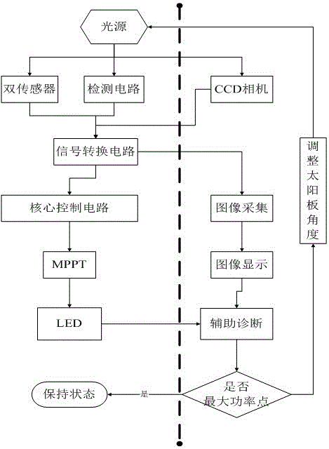
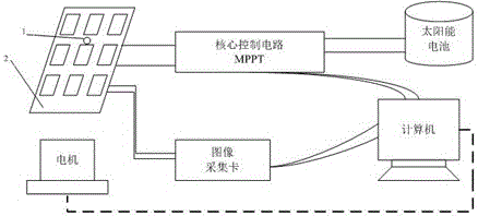
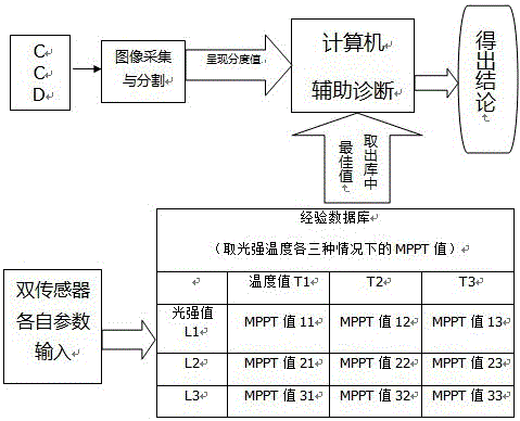
[0022] Such as figure 1 As mentioned above, the entire system can be divided into two parts, bounded by the thick dotted line in the figure, the right part is the core part of the present invention, and the CCD industrial camera collects corresponding light data by accepting natural light sources, and the left part The light intensity sensor, temperature sensor (dual sensor), and current and voltage detection circuit send the collected data to the signal conversion circuit for conversion. The conversion circuit converts the data from the dual sensor and detection circuit and sends it to the single The core control circuit of the chip enters the MPPT system for maximum power tracking; the other end converts the data from the CCD industrial camera and sends it to the image acquisition card for image segmentation algorithm calculations to clearly display the gray value of the light situation corresponding to the current power displayed on the computer. Then the result of MPPT co...


PUM


Abstract

The invention provides a technology for maximum power point tracking and diagnosis of a photovoltaic power generation system. A maximum power point tracking and diagnosis system for the photovoltaic power generation system comprises a light ray collecting module, an image processing module, a maximum power point tracking (MPPT) module and a signal conversion module. The technology comprises the steps of first collecting a light ray intensity image, wherein a collecting system is mainly structurally formed by a light intensity sensor and a temperature sensor; performing light ray image analysis, using a partitioning algorithm to divide the light ray image into several parts which are obviously different in gray values, selecting the partitioning algorithm with an Otsu method and a maximum entropy method as the core, and performing precise image display on a display screen by segmenting out a highest light intensity part. The technology has a very good power tracking effect and can improve working efficiency.

Description

technical field [0001] The invention relates to the field of new energy photovoltaic power generation systems, in particular to an image-aided diagnosis technology for maximum power point tracking of photovoltaic power generation systems. Background technique [0002] With the rapid development of the world today, the resources on the earth are gradually decreasing, and the reduction of resources will inevitably affect the environment and human life. Therefore, the use of new energy has attracted the attention of the world, and our country is also gradually and steadily acting on the road of new energy. The common ones are new energy sources such as wind power and photovoltaics. The maximum power point tracking (MPPT) technology of the power generation system is an important key technology in solar photovoltaic power generation. It means that when the external factors such as temperature and light intensity change, the system can always maintain the maximum power output. In...

Claims


Application Information

Patent Timeline
IPC IPC(8): G05F1/67
CPCG05F1/67Y02E10/56
Inventor 黄昊易灵芝
Owner XIANGTAN UNIV
Learn More