Flyback control circuit and control method

A technology of flyback control and integrated control circuit, which is applied in the direction of control/regulation system, electrical components, and adjustment of electrical variables, etc., which can solve problems such as inability to directly reduce frequency, increase turn-off loss, and large iron loss of magnetic core, and achieve improved Light-load efficiency and the effect of reducing no-load power consumption

Active Publication Date: 2016-11-09
MORNSUN GUANGZHOU SCI & TECH +1
View PDF9 Cites 41 Cited by
  • Summary
  • Abstract
  • Description
  • Claims
  • Application Information

AI Technical Summary

Problems solved by technology

[0004] The loss sources of its large no-load power consumption and low light-load efficiency are mainly: 1. The peak current is large and the effective value of the current is large, which causes large turn-off loss and winding loss; 2. The high switching frequency further increases the turn-off loss, and at the same time The iron loss of the magnetic core is also very large
The peak current is large because the duty cycle of this type of complementary working topology is almost constant under no-load and full-load conditions, so the peak current will be relatively large. At the same time, it cannot be directly Reduce the frequency, which will cause the excitation time to be too long to saturate the transformer and break down the switch tube

Method used


Image

  • Flyback control circuit and control method
  • Flyback control circuit and control method
  • Flyback control circuit and control method

Examples


Embodiment 1

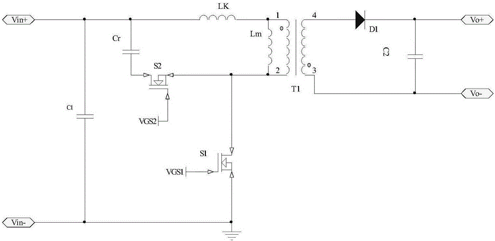
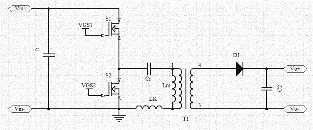
[0035] Such as Figure 4As shown, it is a circuit schematic diagram of the flyback control circuit of the present invention, and the circuit scheme includes: a main power circuit, a clamp circuit, an output rectification and filtering circuit, and a control circuit. The main power circuit is formed by connecting the transformer T1 and the main switching tube S1; the clamping circuit is formed by connecting the clamping switch tube S2 and the clamping capacitor Cr; the output rectifying and filtering module is connected by the output rectifying diode D1 and the output capacitor C2 The control circuit is composed of an integrated control circuit U1, a voltage sampling isolation feedback module U4 and two drive circuit modules U2, U3, the drive circuit module U2 is used to drive the clamp tube S2, and the drive circuit module U3 is used to drive The main switch tube S1. Wherein, the driving circuit module U2 may be a bootstrap type circuit, or may be an isolated driving type cir...


PUM


Abstract

The invention in particular relates to a flyback active-clamp, asymmetrical half-bridge switching converter control circuit and control method. According to the technical scheme of the circuit, a flyback control circuit is provided and controls an integrated control circuit controlling a switch tube and a clamping tube. The integrated control circuit comprises a driving unit of the switch tube, a driving unit of the clamping tube, and a turn-off holding driving unit. When the load is light or zero, the total of a turn-on time of the switch tube, a turn-on time of the clamping tube and a dead zone therebetween forms a single period. The time length of the single period is a fixed value. The turn-on time of the switch tube and that of the clamping tube are in a complementary relation in the single period. The time of the single period and a turn-off holding time form a total working period. Compared with the prior art, while ensuring the efficiency of a conventional circuit and the EMI advantage under a load no less than a light load, the circuit improves the light load efficiency and reduces the zero load power consumption.

Description

technical field [0001] The invention relates to the field of switching converters, in particular to a control circuit and a control method of flyback active clamping and asymmetrical half-bridge switching converters. Background technique [0002] With the rapid development of the field of power electronics, switching converters are used more and more widely, especially people put forward more requirements for switching converters with high power density, high reliability and small size. Generally, traditional low-power AC / DC converters are implemented using flyback topology, which has the advantages of simple structure and low cost; however, ordinary flyback topology is a hard switch, and cannot recover leakage inductance energy, thus limiting the efficiency of small and medium power products And volume, in order to meet the development trend of miniaturization, light weight and modularization of power converters, soft switching technology has become one of the hot spots in ...

Claims


Application Information

Patent Timeline
Patent Type & Authority Applications(China)
IPC IPC(8): H02M3/335
CPCH02M3/33523H02M1/0048Y02B70/10
Inventor 赵永宁黄天华
Owner MORNSUN GUANGZHOU SCI & TECH
Why Eureka
Try Eureka