
Application method for pyrolysis device

A technology of pyrolysis and pyrolysis furnace, which is applied in the direction of direct heating dry distillation, special form dry distillation, petroleum industry, etc. It can solve the problems of large area, large dust content of pyrolysis gas, and increased production cost, so as to reduce dust The content of particles, efficient separation and discharge, and the effect of separation and discharge

Active Publication Date: 2016-11-23
ANHUI UNIVERSITY OF TECHNOLOGY
View PDF5 Cites 0 Cited by
  • Summary
  • Abstract
  • Description
  • Claims
  • Application Information

AI Technical Summary

Problems solved by technology

[0007] Both of the above two pyrolysis equipment adopt the cyclone pyrolysis technology, that is, the raw materials are pyrolyzed through the cyclone in the pyrolysis furnace while the pyrolyzed gas and solid products are directly separated, although the subsequent gas and solid separation is reduced. process, which greatly improves the economic benefits, but there are still the following technical defects that are difficult to overcome: although this cyclone pyrolysis technology can directly separate the gas and solid in the product, it is found through actual testing that the cyclone pyrolysis technology is used to separate The pyrolysis gas still contains a large number of dust particles. In the subsequent treatment, it is usually necessary to use different equipment to remove dust step by step from the pyrolysis gas. Various equipment occupy a large area and increase production costs.
[0008] To sum up, how to overcome the deficiency of large dust content in pyrolysis gas in the prior art is a technical defect that needs to be overcome urgently in the prior art

Method used


Image

  • Application method for pyrolysis device
  • Application method for pyrolysis device
  • Application method for pyrolysis device

Examples


Embodiment 1

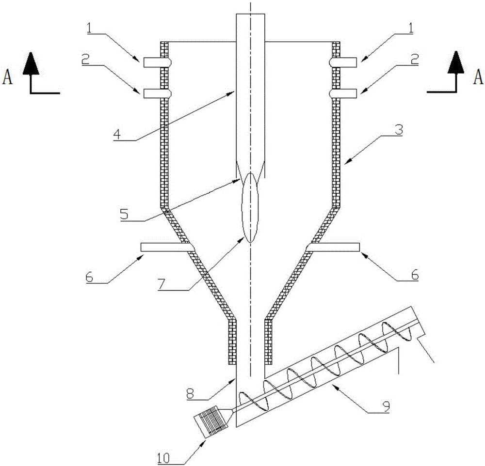
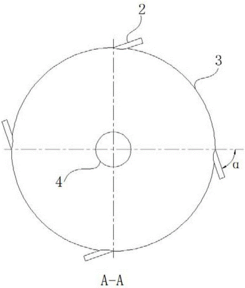
[0068] refer to Figure 1~2 , the pyrolysis device of the present embodiment includes: a pyrolysis furnace 3, and the pyrolysis furnace 3 includes an upper straight section, a tapered section and a lower straight section connected sequentially from top to bottom, and the top side of the upper straight section is circumferentially provided with at least Two primary air inlets 2 (four primary air inlets 2 are provided in this embodiment), and the primary air inlets 2 are not tangent to the top side of the upper straight section; the central cylinder 4 extends from top to bottom into the inside of the upper straight section, and the central axis of the central cylinder 4 coincides with the central axis of the upper straight section.

[0069]In this embodiment, the top side of the upper straight section is provided with at least two primary air inlets 2 along the circumference, and the primary air inlets 2 are not tangent to the top side of the upper straight section. 2 is not ta...

Embodiment 2

[0077] refer to image 3 , the pyrolysis device of the present embodiment, its structure is basically identical with embodiment 1, and its difference is:

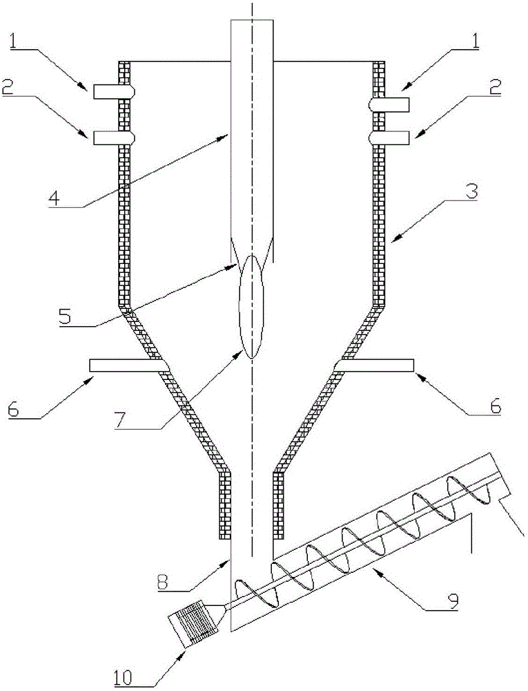
[0078] The pyrolysis device of this embodiment also includes: feed inlet 1, at least two feed inlets 1 (specifically, there are four feed inlets 1 in this embodiment) are sequentially arranged on the side of the upper straight cylinder section from top to bottom; The screening mechanism classifies the pyrolysis raw materials into different batches according to the particle size, and the pyrolysis raw materials of different batches are respectively sent into the feed inlet 1 of different heights.

[0079] In this embodiment, the screening mechanism classifies the pyrolysis raw materials into different batches according to the particle size, and the pyrolysis raw materials of different batches are respectively sent into the feed inlets 1 of different heights, at least two feed inlets 1 are from the top And the bottom is arra...

Embodiment 3

[0081] The pyrolysis device of the present embodiment, its structure is basically identical with embodiment 1, and its difference is:

[0082] The pyrolysis device of this embodiment further includes: an ellipsoid 7 located below the central cylinder 4 , and the upper end of the ellipsoid 7 protrudes into the interior of the central cylinder 4 .

[0083] In this embodiment, the ellipsoid 7 is located below the central cylinder 4, and the upper end of the ellipsoid 7 extends into the interior of the central cylinder 4, and the pyrolysis gas after pyrolysis contains a large amount of dust particles, because the upper end of the ellipsoid 7 extends Therefore, when the pyrolysis gas containing dust particles enters the interior of the center cylinder 4 from the entrance below the center cylinder 4, the flow area decreases suddenly, and the flow velocity of the pyrolysis gas increases, but the pyrolysis gas in the pyrolysis gas Due to the relatively high density of dust particles, ...


PUM

PropertyMeasurementUnit
thicknessaaaaaaaaaa

Abstract

The invention discloses an application method for a pyrolysis device and belongs to pyrolysis equipment in the chemical industry. The application method for the pyrolysis device comprises the following steps that firstly, primary air is led into a primary air inlet, and rotational flow is formed in a pyrolysis furnace; secondly, a pyrolysis raw material is fed into a feeding port, under the action of the rotational flow, the pyrolysis raw material rotates and sinks to the bottom of the pyrolysis furnace and is pyrolyzed; thirdly, a solid product produced through pyrolysis constantly sinks to a discharging port in the lower end of a lower straight cylinder segment and then is conveyed to the exterior of the furnace through a screw conveyor, and a gas product produced through pyrolysis is discharged out of the furnace through a center cylinder; fourthly, the air volume of secondary air is adjusted, and the diameters of the solid product conveyed to the exterior of the furnace through the screw conveyor are controlled to be smaller than 2 mm. The application method mainly overcomes the defect that in the prior art, the dust load in pyrolysis gas is large.

Description

technical field [0001] The invention relates to pyrolysis equipment in the chemical industry, more specifically, to a method for using a pyrolysis device. Background technique [0002] Pyrolysis technology is to heat organic matter to 500-1000°C in anaerobic or oxygen-deficient state, so that organic matter in solid waste can be converted into stored energy mainly consisting of gas, fuel oil and pyrolytic charcoal. Due to the anaerobic decomposition and reducing atmosphere, it can reduce the secondary pollution of sulfur, nitrogen, heavy metals and other harmful components in the waste to the environment, and there is no need for expensive scrubbing devices in the process. [0003] Combustion of fossil fuels has caused most of the environmental pollution problems and seriously affected people's quality of life. Substance thermal conversion utilization technology. According to the statistics of the National Development and Reform Commission, in 2013, the actual domestic con...

Claims


Application Information

Patent Timeline
Patent Type & Authority Applications(China)
IPC IPC(8): C10B53/02C10B49/12
CPCC10B49/12C10B53/02Y02E50/10
Inventor 陈光朱宝忠王恒达
Owner ANHUI UNIVERSITY OF TECHNOLOGY
Learn More