
Car high beam and dipped headlight module based on laser technique

A laser technology, far and near light technology, used in electric light sources, motor vehicles, road vehicles, etc., can solve the problems of complex processing of mirrors and prisms, difficulty in precise positioning, interference with optical effects, etc. Powerful, simple cooling system, uniform light output

Active Publication Date: 2016-11-23
CHANGZHOU XINGYU AUTOMOTIVE LIGHTING SYST CO LTD
View PDF6 Cites 2 Cited by
  • Summary
  • Abstract
  • Description
  • Claims
  • Application Information

AI Technical Summary

Problems solved by technology

However, at present, the small size and high power laser diodes are all less than 2W, so when used in the field of high power lighting, it is necessary to use a multi-light source system
[0003] However, the existing optical module has an open space optical path inside the lamp, which is not closed, and the optical effect is easily disturbed by dust or impurities. The processing of reflectors and prisms is complicated, and the optical path requires precise positioning to achieve optical effects. However, in actual operation , due to the use of two-way optical modules, it is very difficult to accurately locate, and the shock resistance is poor. When used in car lights, it is easy to move and affect the optical effect
Furthermore, the use of a space optical path leads to a large module size, especially after the lamp body is damaged, because the high-power blue laser that has not been sealed and packaged may cause personal injury, and there are certain hidden dangers in installation

Method used


Image

  • Car high beam and dipped headlight module based on laser technique

Examples


Embodiment Construction

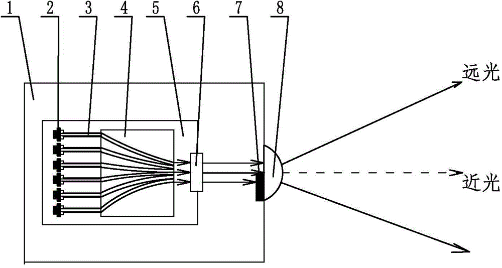
[0012] See figure 1 As shown, the automobile high and low beam lamp module based on laser technology of the present invention includes a lamp body 1 and a laser illumination light source and a PES lens 8 installed on the lamp body 1 .

[0013] See figure 1 As shown, the laser illumination light source of the present invention includes six blue laser diodes 2 with a wavelength of 450nm to form a blue laser array, the output ends of each blue laser diode 2 are docked with the input ends of the respective corresponding optical fibers 3, and the output ends of each optical fiber 3 It is docked with the input end of each corresponding optical waveguide on the quartz substrate optical waveguide chip 4, the center of each blue laser diode 2 coincides with the center of each optical fiber input end, and the input end of each optical waveguide on the quartz substrate optical waveguide chip 4 and the corresponding The centers of the fiber output ends coincide. Realize the docking of t...


PUM


Abstract

The invention relates to a car high beam and dipped headlight module based on the laser technique. A laser lighting source and a PES lens are installed on a lamp body. Six blue laser diodes with the wavelength being 450 nm on the laser lighting source and optical fibers corresponding to the six blue laser diodes are in butt joint with the input ends of corresponding optical waveguides on a quartz substrate optical waveguide chip. Optical paths converge at the emergent end of the quartz substrate optical waveguide chip to form even linear emergent light with the wavelength being 450 nm. A light entering face and a light exiting face of a yellow phosphorus lens used for converting the linear emergent light into white parallel beams are arranged parallel to each other. The blue laser diodes, the optical fibers, the quartz substrate optical waveguide chip and the yellow phosphorus lens are fixed and packaged into a whole through colloid. The PES lens is located in front of the yellow phosphorus lens. The PES lens and a light shield plate with an emitting light type being adjustable are used for producing high beams and dipped beams. The car high beam and dipped highlight module provided by the invention has the advantages of being small in size, capable of being packaged independently and improving the vibration resistance and damage resistance, and not prone to interference caused by dust or impurities.

Description

technical field [0001] The invention relates to an automobile high and low beam lamp module based on laser technology, which belongs to the technical field of automobile lamp lighting. Background technique [0002] With the continuous development of car lighting technology, more and more new technologies and new light sources are used for the far and near beam lighting of car lights, from the initial halogen light source to the xenon light source to the widely used LED light source today, and LED due to The problem of heat dissipation leads to the need for a very complicated cooling system, which indirectly increases the volume and quality of the system. Compared with traditional light sources such as metal lamps, high-pressure gas lamps and LEDs, lasers have the advantages of low energy consumption, pure light color, high brightness, good directionality, and small size of the light distribution mechanism. However, at present, the small-sized high-power laser diodes are all...

Claims


Application Information

Patent Timeline
Patent Type & Authority Applications(China)
IPC IPC(8): F21S8/10F21V19/00F21V17/00F21W101/02F21W101/10F21W107/10
Inventor 邓亮张立杨夏军蒋荡华
Owner CHANGZHOU XINGYU AUTOMOTIVE LIGHTING SYST CO LTD
Learn More