Low-orbit positioning load aluminium alloy horn antenna and manufacturing method thereof

A horn antenna, aluminum alloy technology, applied in antennas, waveguide horns, electrical components, etc., can solve the problems of easy boiling and evaporation of Al elements, heavy weight of horn antennas, and large residual porosity, etc., to improve the molding density and antenna performance. , Antenna processing cycle and cost reduction, the effect of optimizing the molding process

Active Publication Date: 2016-11-23
TSINGHUA UNIV
View PDF3 Cites 8 Cited by
  • Summary
  • Abstract
  • Description
  • Claims
  • Application Information

AI Technical Summary

Problems solved by technology

However, for refractory alloys represented by aluminum alloys, affected by their inherent physical properties such as melting point, density, thermal conductivity, melt tension, and viscosity, there are high reflectivity (low absorption) and easy formation of oxidation in the laser forming process. Layer, Al element is easy to boil and evaporate, low melt viscosity, high thermal conductivity, high thermal expansion coefficient, high solidification shrinkage rate, and relatively wide liquid-solid line interval, etc., so it is easy to spheroidize the molten pool , Large residual porosity, deformation and bending, cracks, low dimensional accuracy and large surface roughness, etc., affect the performance of the aluminum alloy horn antenna, and do not meet the final antenna use requirements such as gain and structural density.
In addition, the existing horn antenna still has the disadvantage of heavy weight, which requires further lightening

Method used


Image

  • Low-orbit positioning load aluminium alloy horn antenna and manufacturing method thereof
  • Low-orbit positioning load aluminium alloy horn antenna and manufacturing method thereof
  • Low-orbit positioning load aluminium alloy horn antenna and manufacturing method thereof

Examples


Embodiment Construction

[0055] The principles and features of the present invention are described below, and the examples are only used to explain the present invention, but not to limit the scope of the present invention.

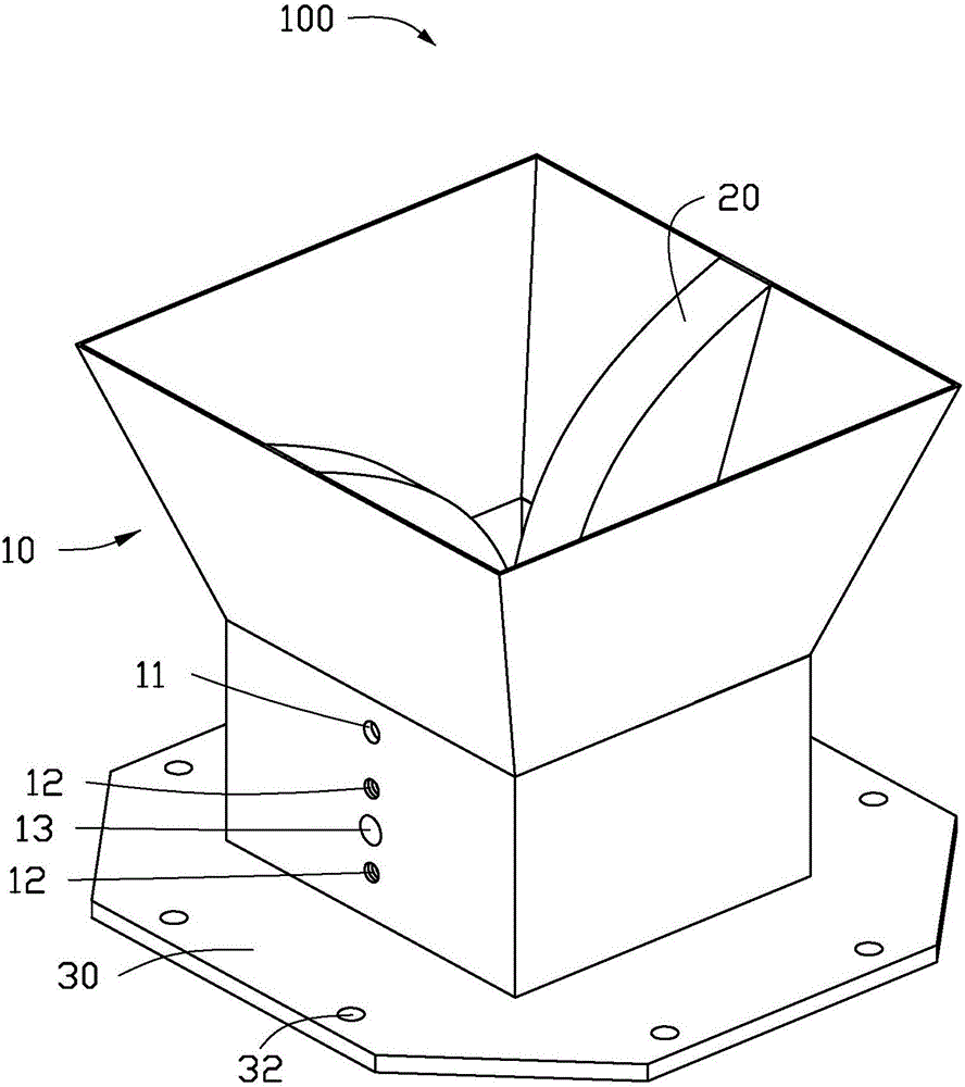
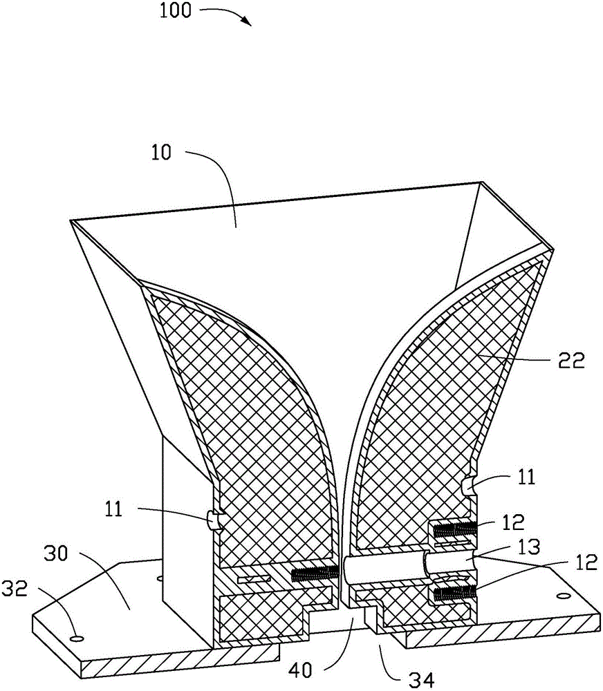
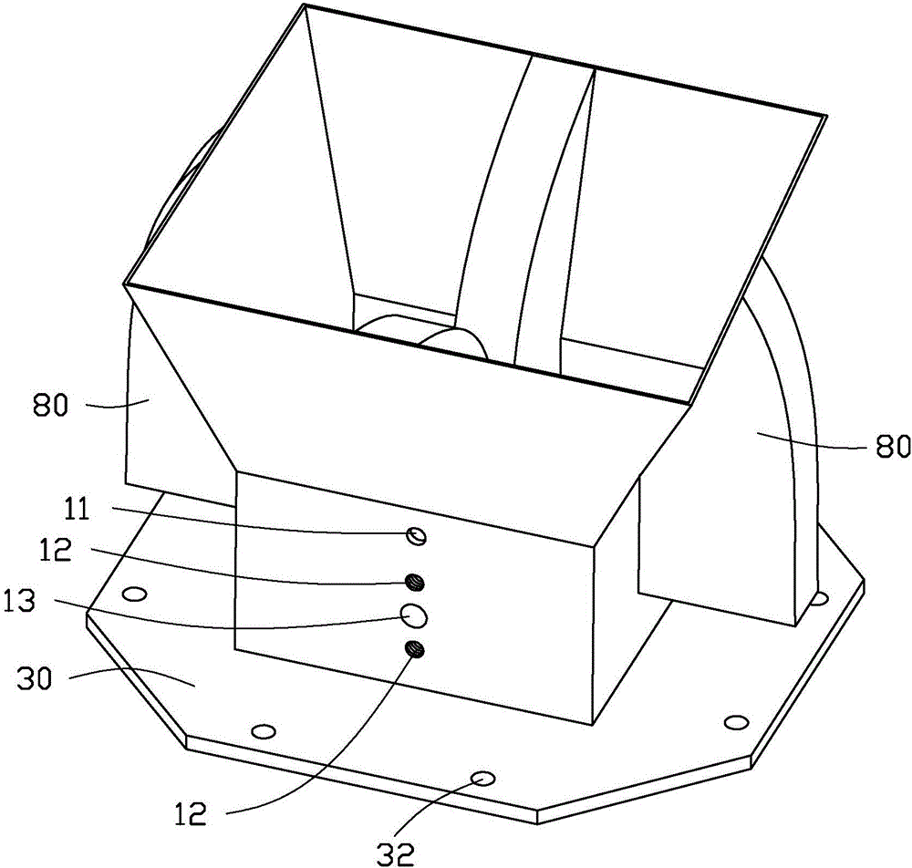
[0056] See Figure 1 to Figure 3 , the embodiment of the present invention provides an additive manufacturing method for a horn antenna 100 facing a low-orbit positioning load, which includes the following steps:

[0057] Step 1), designing the horn antenna 100 according to the requirements of the additive manufacturing process, the antenna ridge 20 of the horn antenna 100 is a grid design, the bottom of the antenna resonant cavity 40 is an opening design, and the bottom of the antenna ridge 20 has a pillar design, and Design of the outer ridge 40 of the antenna;

[0058] Step 2), performing antenna additive manufacturing processing;

[0059] In step 3), post-processing is performed on the processed antenna to obtain a final usable antenna, and the post and the outer ridge 40 o...


PUM

PropertyMeasurementUnit
Diameteraaaaaaaaaa
Thicknessaaaaaaaaaa

Abstract

The invention relates to a low-orbit positioning load antenna manufacturing method and especially relates to a low-orbit positioning load aluminium alloy horn antenna material increase manufacturing method. The method comprises an antenna ridge and bottom grid design, an antenna resonance cavity bottom opening design, an inner ridge bottom pillar design, an antenna outer ridge design and a laser forming and remelting process flow parameter design. The grid design can reduce the weight of an antenna to enable the antenna to be lighter; the antenna resonance cavity bottom opening design facilitates polishing of the inner wall of a resonance cavity; the inner ridge bottom pillar design can ensure 90-degree geometrical relationship of the inner ridge bottom and the side wall of the resonance cavity, thereby improving performance of the antenna; the antenna outer ridge design is to add two supports, which are same in size and thickness with inner ridges at the antenna outside thin-wall positions to ensure that the thin walls can be held during printing, thereby preventing stress deformation; and when the antenna is formed, removing and polishing are carried out. The problem that it is difficult to print the aluminium alloy is overcome through a customized 3D printing flow. The weight of the antenna designed through the method above is reduced by 2 / 3, and the antenna is of great importance in space-borne application.

Description

technical field [0001] The invention relates to an antenna manufacturing method, in particular to an additive manufacturing method of an aluminum alloy horn antenna facing a low-orbit positioning load, and belongs to the field of additive manufacturing. Background technique [0002] The low-orbit positioning payload includes low-orbit navigation enhancement and low-orbit spectrum scanning functions, and generally requires the antenna to have a wide frequency range and light weight. In order to meet the requirements of a wider frequency range, a horn antenna is generally used. Antennas manufactured by traditional manufacturing methods have large mass, many components and long cycle times. Using innovative manufacturing methods to reduce quality, reduce the number of components and manufacturing cycle has become a direction for low-orbit positioning payload antenna technology. [0003] In recent years, 3D printing technology, or additive manufacturing processing technology, h...

Claims


Application Information

Patent Timeline
IPC IPC(8): H01Q13/02
CPCH01Q13/0275H01Q13/0283
Inventor 黄振赵砚陈曦刘伟王梦璐
Owner TSINGHUA UNIV
Why Eureka
Try Eureka