System and process for storing and releasing electric energy

A storage system and process technology, applied in the direction of storage of electric energy systems, electrical components, etc., can solve problems such as unsatisfactory power development, low efficiency, energy storage limitations, etc., to solve large-scale storage problems, ease supply and demand, improve storage The effect of energy efficiency

Active Publication Date: 2016-11-23
SINOPEC ENG +1
View PDF5 Cites 1 Cited by
  • Summary
  • Abstract
  • Description
  • Claims
  • Application Information

AI Technical Summary

Problems solved by technology

The most mature and common energy storage method is pumped storage in physical energy storage, but its application is limited by geological conditions and other conditions, and it is far from meeting the needs of electric power development; and a major defect of compressed air energy storage in physical energy storage due to low efficiency
Batteries in chemical energy storage have small power storage capacity, short life, and low energy density, which limits their ability to realize large-scale power station energy storage, while the way of electrolyzing water and hydrogen to store electrical energy is limited by defects such as the difficulty of hydrogen storage and transportation.

Method used


Image

  • System and process for storing and releasing electric energy
  • System and process for storing and releasing electric energy

Examples


Embodiment 1

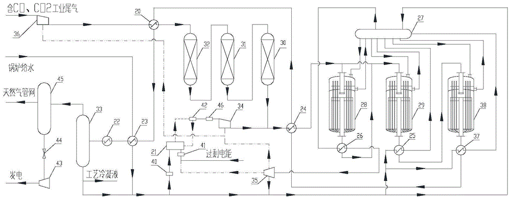
[0061] like figure 1 As shown, M=3.0 containing CO 2 , CO industrial tail gas, after dedusting and purification treatment, is pressurized and sent to 1# raw material heater 20 through carbon oxide gas compressor 36, and the purified gas after preheating passes through hydrolysis reactor 32, fine desulfurization reactor 31, deoxidation, After the denitrification reactor 30, the obtained purified gas has a sulfur content of 65ppb, a nitrogen content of 150ppm, and an oxygen content of 270ppm.

[0062] The wind power that is difficult to store and grid-connected is rectified by the AC / DC rectifier 41 and introduced into the manganese salt solution electrolytic cell 21 . The manganese salt solution electrolytic cell 21 obtains metal manganese, and the precipitated metallic manganese reacts with dilute sulfuric acid in the manganese dilute acid reaction device 42 to generate a large amount of hydrogen and manganese salt solution, and the manganese salt solution returns to the elec...

Embodiment 2

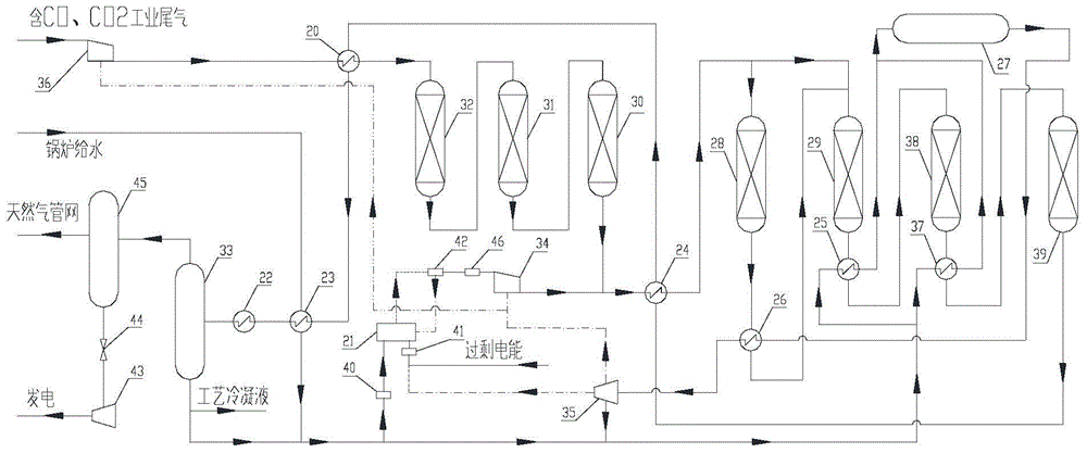
[0072] like figure 2 As shown, embodiment 2 is basically the same as embodiment 1, and the difference is: 1) use four radial bed reactors with diversion cone heat transfer instead of heat pipe reactor; 2) 1# methanation reactor outlet is set Steam superheater 26; 3) Medium pressure waste boiler 25 and medium pressure waste boiler 37 are installed at the outlets of 2# and 3# methanation reactors respectively; 4) 3# and 4# methanation reactors are connected in series. The specific process is as follows:

[0073] The electric energy generated by wind power and solar energy, which is difficult to store and grid-connected, is rectified by the AC / DC rectifier 41 and then introduced into the manganese salt solution electrolytic cell 21 . The manganese salt solution electrolytic cell 21 obtains metal manganese, and the precipitated metallic manganese reacts with dilute sulfuric acid in the manganese dilute acid reaction device 42 to generate a large amount of hydrogen and manganese ...


PUM


Abstract

The invention discloses a system and a process for storing and releasing electric energy based on a methanation reaction. The system and the process each comprise a carbon-oxygen-containing purification system, a gas generation system, a methanation system, a vapor heating system of the methanation system, a product separation system, a product storage system and a gas power generation system. Compared with the prior art, the system and the process provided by the invention can realize the purposes of performing peak regulation of the existing power grid and improving electric energy utilization efficiency through storing excess electric energy in the form of a substitute natural gas, and generating electric energy by a gas turbine power generation system through utilizing the substitute natural gas when the power utilization peak comes.

Description

technical field [0001] The present invention relates to a system and process for storing and releasing electrical energy. Background technique [0002] At present, more than 70% of carbon emissions come from coal combustion, and then come from oil, natural gas, cement and other industries in descending order. This not only brings about the global greenhouse effect and frequent occurrence of extreme weather, but also wastes a lot of energy. resource. In addition, due to the bottleneck of access to the Internet, my country's wind power and solar energy seriously restrict the development of wind power and solar energy industries. A large loss of electric energy and loss of equipment and line network in the long term. The increasingly serious environmental problems caused by carbon emissions, the recycling of resources, and the improvement of energy efficiency have prompted people to seek solutions to these problems. [0003] According to incomplete statistics, my country's cu...

Claims


Application Information

Patent Timeline
IPC IPC(8): H02J15/00
Inventor 张旭戴文松王子宗蒋荣兴
Owner SINOPEC ENG
Why Eureka
Try Eureka