
A furniture table leg solid wood parts dual -end -end -of -cut corner punch punching machine and processing method

A technology of punching machine and solid wood, applied in the direction of wood processing appliances, manufacturing tools, sawing components, etc., can solve the problems of low efficiency, time-consuming and labor-intensive, downsizing and increasing efficiency, etc., to reduce labor intensity, improve production efficiency, reduce The effect of labor

Active Publication Date: 2018-12-04
美克数创赣州家居智造有限公司 +2
View PDF7 Cites 2 Cited by
  • Summary
  • Abstract
  • Description
  • Claims
  • Application Information

AI Technical Summary

Problems solved by technology

[0002] At present, the processing of solid wood parts such as furniture table legs requires multiple processes. First, the length of the solid wood board needs to be fixed, and then the square head triangle is sawed. Finally, holes need to be punched on a punching machine. At least three pieces of equipment are required for processing, that is, double-ended fixed-length saws, triangular saws, and drilling machines. The three pieces of equipment are set up independently, and semi-finished parts need to be manually moved in the middle, which is laborious and inefficient; therefore, for leg parts Double-end fixed length, sawing square head triangle, and drilling are integrated and processed on one equipment, instead of multiple equipment processing to achieve the purpose of reducing staff and increasing efficiency

Method used


Image

  • A furniture table leg solid wood parts dual -end -end -of -cut corner punch punching machine and processing method
  • A furniture table leg solid wood parts dual -end -end -of -cut corner punch punching machine and processing method
  • A furniture table leg solid wood parts dual -end -end -of -cut corner punch punching machine and processing method

Examples


Embodiment Construction

[0035] In order to further understand the invention content, characteristics and effects of the present invention, the following examples are given, and detailed descriptions are as follows in conjunction with the accompanying drawings:

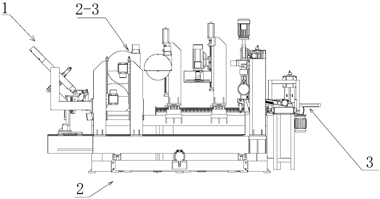
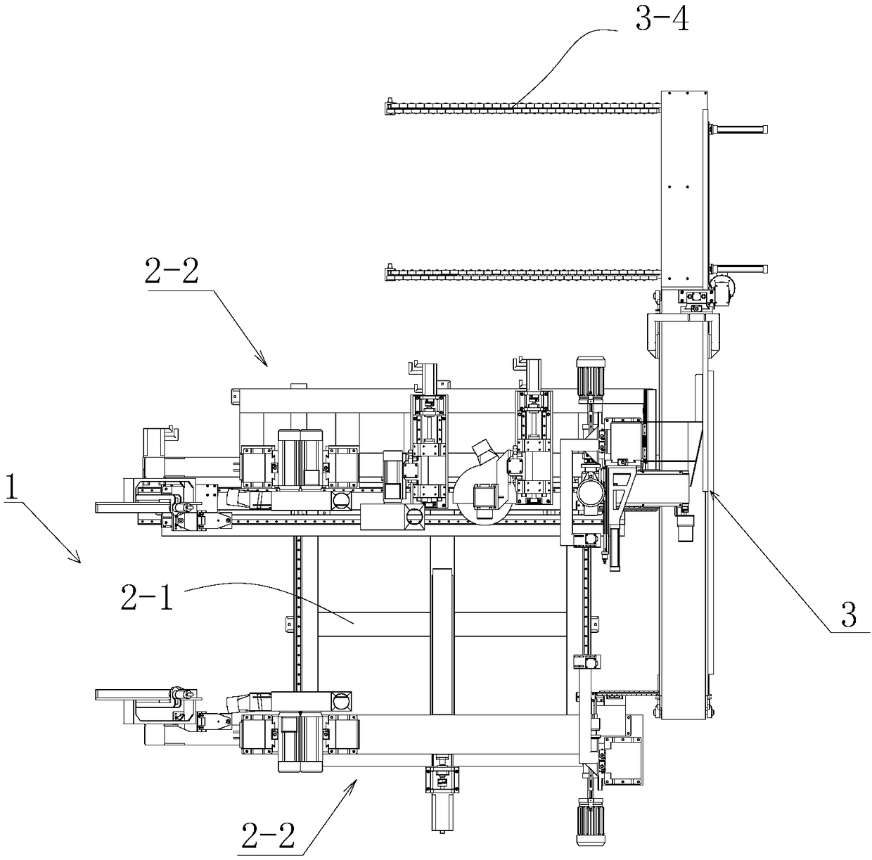
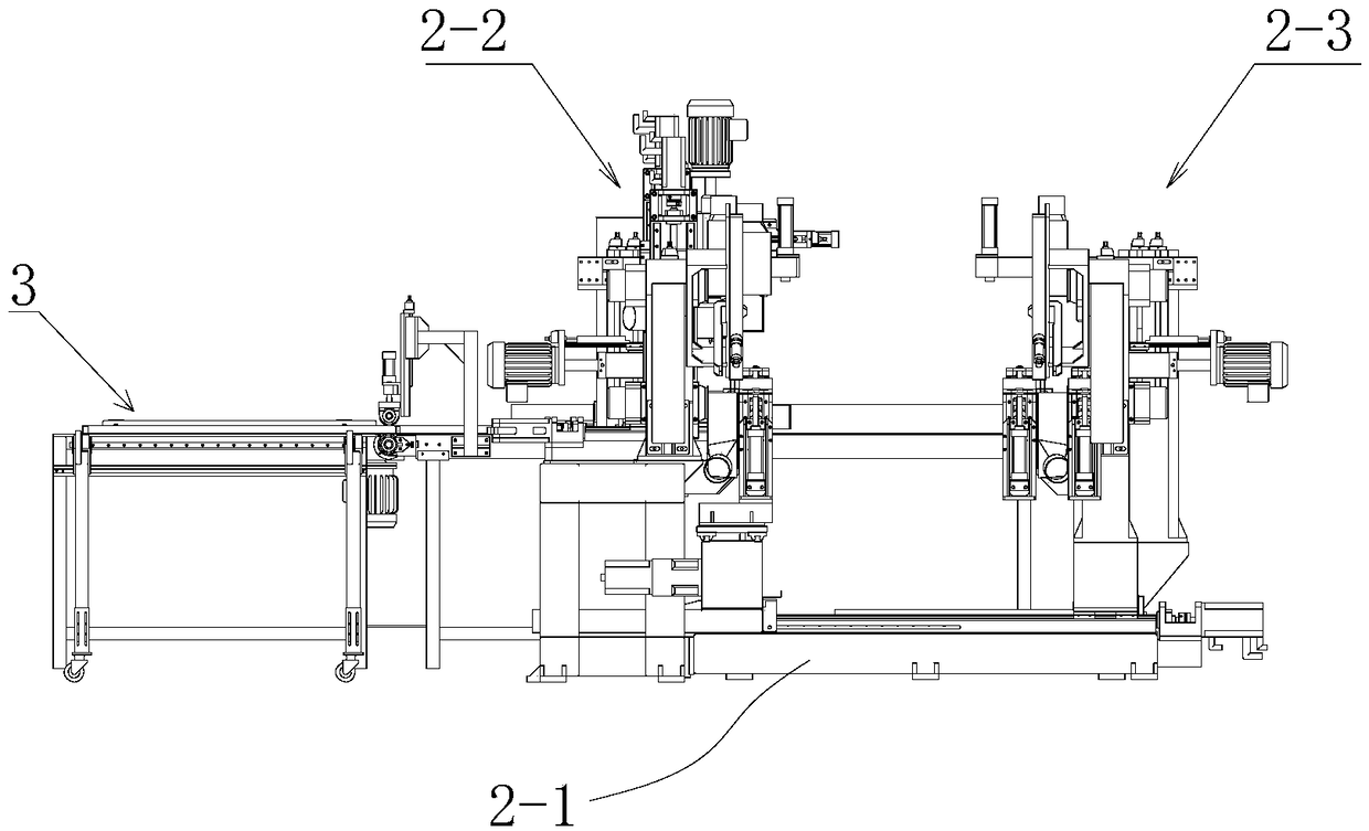
[0036] see Figure 1 to Figure 6 , a double-end fixed-length corner-cutting punching machine for solid wood parts such as furniture table legs, including an upper material bin 1, a fuselage 2, and a finished material conveying mechanism 3; At the discharge end of the fuselage 2, a finished material conveying mechanism 3 is installed; the fuselage 2 includes a machine base 2-1, and a fixed workstation 2-1 is installed on one side of the machine base 2-1 along the material feeding direction. 2. Mobile workstations 2-3 are installed on the other side; the fixed workstations are equivalent to the positioning reference on one side, and are adjusted according to the length of the actual processed solid wood parts; linear slides perpendicular to the...


PUM


Abstract

The invention relates to a double-end fixed length corner cutting and perforating machine and method for furniture table leg solid wood components. The double-end fixed length corner cutting and perforating machine comprises a feeding bin, a machine body and a finished material conveying mechanism; the finished material conveying mechanism is mounted at the discharging end of the machine body; a fixed work station is mounted on a base of the machine body; a movable work station is mounted on the other side; a linear sliding rail is mounted on the base, the movable work station is mounted on the linear sliding rail, and a servo driving device is mounted on the base; a fixed length saw set, a vertical corner cutting saw set, a fixed horizontal corner cutting saw set, a horizontal drill machining set and a vertical drill machining set are mounted on a fixed workbench; a movable fixed length saw set is mounted on a movable workbench in the material feeding direction; a movable horizontal drill machining set is mounted at the position, corresponding to the fixed horizontal drill machining set, of the movable work station; a clamping conveying device is further arranged. Compared with traditional single machining, production efficiency is greatly improved, labor intensity is reduced, labor force is reduced, and the aims of downsizing staffs and improving efficiency are achieved.

Description

technical field [0001] The invention belongs to the technical field of processing solid wood parts such as furniture table legs, and in particular relates to a double-end fixed-length cutting angle punching machine and a processing method for solid wood parts such as furniture table legs. Background technique [0002] At present, the processing of solid wood parts such as furniture table legs requires multiple processes. First, the length of the solid wood board needs to be fixed, and then the square head triangle is sawed. Finally, holes need to be punched on a punching machine. At least three pieces of equipment are required for processing, that is, double-ended fixed-length saws, triangular saws, and drilling machines. The three pieces of equipment are set up independently, and semi-finished parts need to be manually moved in the middle, which is laborious and inefficient; therefore, for leg parts Double-end fixed length, sawing square head triangle, and drilling are inte...

Claims


Application Information

Patent Timeline
Patent Type & Authority Patents(China)
IPC IPC(8): B27B5/06B27B25/00B27C3/04B27G3/00B27G19/02
CPCB27B5/061B27B5/063B27B25/00B27C3/04B27G3/00B27G19/02
Inventor 曹辉琪许海
Owner 美克数创赣州家居智造有限公司
Learn More