Gas-solid phase continuous reaction device with heat transfer enhancing function

A technology for strengthening heat transfer and reaction devices, applied in chemical/physical/physical-chemical fixed reactors, feeding devices, chemical instruments and methods, etc., can solve problems such as inability to achieve continuous operation, and improve equipment utilization. , avoid manual operation, easy to control the effect

Active Publication Date: 2016-12-07
NORTHWEST UNIV(CN)
View PDF5 Cites 6 Cited by
  • Summary
  • Abstract
  • Description
  • Claims
  • Application Information

AI Technical Summary

Problems solved by technology

[0003] The purpose of the present invention is to propose a new structure in order to overcome the deficiency that the above-mentioned prior art cannot realize continuous operation. The device utilizes the orderly opening and closing of the gas-liquid phase flow channel to realize the automatic control of the gas-solid phase reaction

Method used


Image

  • Gas-solid phase continuous reaction device with heat transfer enhancing function
  • Gas-solid phase continuous reaction device with heat transfer enhancing function
  • Gas-solid phase continuous reaction device with heat transfer enhancing function

Examples


Embodiment 1

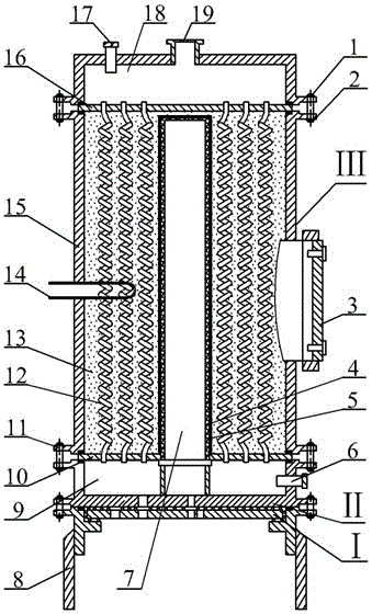
[0044] Aiming at the hydrogen absorption and desorption process of metal hydride hydrogen storage reaction, the structural schematic diagram of the present invention is as attached Figure 1-4 shown. The present invention will be further described below in conjunction with the accompanying drawings.

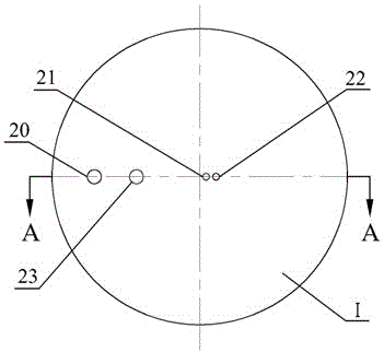
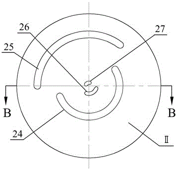
[0045] attached Figure 1-3 As shown, the cooling fluid inlet (20), the hot fluid inlet (23), the gas phase inlet (21) and the gas phase outlet (22) are arranged radially on the rotating disk (I), and the cooling fluid inlet (22) is arranged on the fixed disk (II) according to certain rules. Fluid inlet groove (25), thermal fluid inlet groove (24), gas phase inlet groove (27) and gas phase outlet groove (26), the distance between each gas phase and fluid inlet and outlet groove (24, 25, 26, 27) and the center of the disk It is equal to the distance from the corresponding hole on the rotating disk to the center of the disk, and the groove width is equal to the diameter of the co...

Embodiment 2

[0053] For the hydrogen storage reaction that requires vacuuming and ensuring pressure safety, the inventor added a vacuuming passage and a safety valve passage on the basis of the four-hole solution in Example 1 to further ensure the thoroughness and safety of the reaction. Attached below Figure 5-8 The present invention will be further described by taking the complete hydrogen storage reaction process as an example.

[0054] When the rotating disk is turned until the vacuum port (29) is connected to the vacuum groove (30) of the fixed disk (II), gas phase desorption or desorption under vacuum conditions can be realized, and the residual in the device can also be extracted before the initial reaction. gas.

[0055] as attached Image 6 , 7 As shown, a safety valve interface (28) is added on the rotating disk (Ⅰ), which can be connected with a safety valve and a pressure gauge. When the rotating disk rotates to the safety valve interface (28) and the safety valve interface...

Embodiment 3

[0063] The inventor used the commercial simulation software COMSOL to establish a three-dimensional mathematical model of the present invention, and carried out detailed numerical calculations on its hydrogen absorption and desorption process, explored the influence of different initial reaction fractions on the reaction process, and obtained the optimal initial reaction The optimal scheme of the hydrogen absorption and desorption cycle duration under the fractional ratio and the length of each channel on the fixed plate corresponding to each stage. as follows:

[0064] attached Figure 9 It is the time-consuming distribution diagram of the hydrogen absorption and desorption reaction of the device under different initial reaction fractions. The degree of control reaction is certain, that is, △X=0.8. It was found that, limited by the mechanism of hydrogen absorption and desorption reaction, the larger the initial reaction fraction of hydrogen absorption, the longer the reacti...


PUM


Abstract

The invention discloses a gas-solid phase continuous reaction device with a heat transfer enhancing function. The gas-solid phase continuous reaction device comprises a rotating disc (I), a fixed disc (II) and a reactor (III), wherein a gas phase inlet, a gas phase outlet, a cold fluid inlet and a hot fluid inlet are distributed in the rotating disc along the radial distribution; a gas phase inlet groove, a gas phase outlet groove, a cold fluid inlet groove and a hot fluid inlet groove are distributed in the fixed disc; distances between the grooves and the center of the rotating disc are equal to distances between corresponding holes of the rotating disc and the center of the rotating disc, the width of each groove is equal to the diameter of a corresponding hole, and a central angle of each groove (namely groove length) depends on reaction time period required to be controlled by a user. The gas-solid phase continuous reaction device has the characteristics of continuous operation, controllable reaction time, high equipment utilization rate, stable technological parameters, convenience in operation, guarantee of production safety, simple structure, low cost and the like.

Description

technical field [0001] The invention relates to a gas-solid phase reaction device with enhanced heat transfer, especially suitable for gas-solid phase chemical reactions such as metal hydride hydrogenation / dehydrogenation and application solutions, aiming to solve the current problems involving the input / removal of reaction heat The practical problem that the gas-solid phase chemical reaction cannot realize continuous automatic control. Background technique [0002] At present, the gas-solid phase reactors at home and abroad that involve enhanced heat transfer in the reaction process mainly include tubular reactors (Int. JHydrogen. Energ., 2010, 35(1):321–328), U-shaped gas-solid phase reactors (Int. . J Hydrogen.Energ.,2003, 28 (3): 329-333), multi-bundle coupled reactor (Appl. Therm. Eng., 1998, 18(6): 457-480), arcuate plate reactor ( Chinese invention patents 201010510847.6, 200510042823.1), ring-disk reactors, microchannel reactors (Shanghai: 2008 Chemical Machinery An...

Claims


Application Information

Patent Timeline
Patent Type & Authority Applications(China)
IPC IPC(8): B01J19/24B01J19/00B01J4/00
CPCB01J4/007B01J19/0013B01J19/0053B01J19/24B01J19/243B01J2204/002B01J2219/00081B01J2219/00099
Inventor 王玉琪何曾李珊珊宋静郑岚杨福胜吴震张早校
Owner NORTHWEST UNIV(CN)
Why Eureka
Try Eureka