Method for controlling spin wave transmission

A spin wave and waveguide technology, applied in the field of control spin wave transmission, can solve the problems of high energy consumption, complex design, low system reliability, etc., achieve the effect of low power efficiency, reduce complexity, and promote compatibility

Active Publication Date: 2016-12-07
HUAZHONG UNIV OF SCI & TECH
View PDF5 Cites 14 Cited by
  • Summary
  • Abstract
  • Description
  • Claims
  • Application Information

AI Technical Summary

Problems solved by technology

[0005] In view of the above defects or improvement needs of the prior art, the present invention provides a spin wave transmission control method based on an electric field. By applying an electric field, the intensity of the internal exchange interaction of the magnetic waveguide material is adjusted, and then the dispersion relationship of the spin wave is adjusted to realize the control of the spin wave. Precise control of the electric field of the rotary wave transmission, thereby solving the technical problems of complex design, high energy consumption and low system reliability existing in traditional magnetic field control methods

Method used


Image

  • Method for controlling spin wave transmission
  • Method for controlling spin wave transmission
  • Method for controlling spin wave transmission

Examples


Embodiment 1

[0034]This embodiment reveals the change law of the exchange interaction strength of the magnetic waveguide under the action of the electric field along the normal direction of the waveguide plane through the first principle calculation.

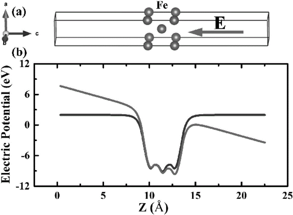
[0035] The calculation uses a model such as image 3 As shown in (a), it is 3 layers of bcc Fe(001) atomic layers, and its vacuum layer thickness is The electric field along the c-axis direction is introduced by the dipole layer method, and the applied electric field strength ranges from -5V / nm to 5V / nm. The calculations are based on the first-principles VASP software package, and the exchange integral J is derived from the energy difference between the antiferromagnetic and ferromagnetic states.

[0036] To simplify the description, the image 3 The iron atoms in (a) are marked as 1, 2, 3 from left to right. Considering only the nearest neighbor exchange interaction, the ferromagnetic state energy E can be obtained F and the antiferrom...

Embodiment 2

[0046] This example reveals the influence of the electric field modulation exchange effect on the spin wave transmission, the corresponding change law of the spin wave number, phase velocity, and wavelength through micromagnetic simulation, and proves the feasibility of using the electric field to regulate the exchange constant to control the spin wave transmission.

[0047] The simulation is carried out using the OOMMF software package based on the LLG equation, and the calculation especially considers the effect of the electric field modulation exchange interaction:

[0048] d m → d t = - | γ | 1 + α 2 m → × ( ...

Embodiment 3

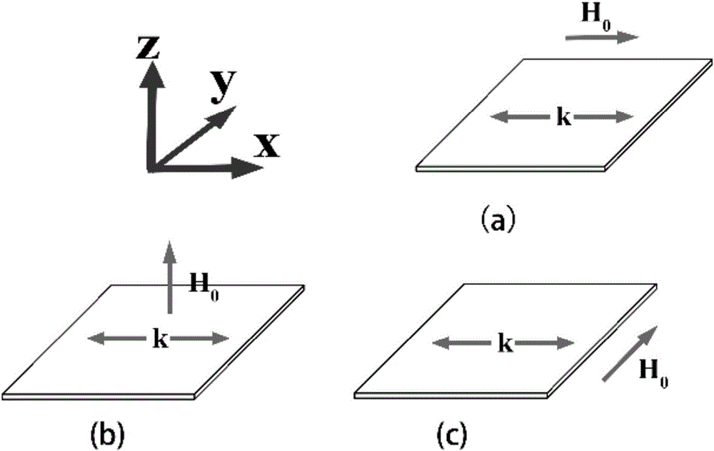
[0063] The bias magnetic field is along the x direction in the plane, and the others are the same as in Embodiment 2. The results show that the dispersion relationship of the reverse body wave can be effectively adjusted by modulating the exchange interaction intensity by an external electric field, and the wave number, phase velocity, wavelength and group velocity of the spin wave can be effectively adjusted, so the external electric field can effectively control the reverse body wave transmission.


PUM


Abstract

The invention discloses a method for controlling spin wave transmission and belongs to the field of spintronics. According to the method, through applying an electric field on a spin wave guide structure, the strength of exchange interaction in a magnetic waveguide material can be effectively changed. An exchange constant is controlled through the electric field, so that the spin wave dispersion relation can be regulated to realize a purpose of controlling the spin wave transmission. The exchange interaction is controlled through the electric field, so that the local precise control of the spin wave transmission can be realized at ultra-low power consumption to provide the possibility for actual application of an ultra-low-power magnonics device compatible with a CMOS (Complementary Metal-Oxide-Semiconductor Transistor) technological process.

Description

technical field [0001] The invention belongs to the technical field of spin electronics, and more specifically relates to a method for controlling spin wave transmission. Background technique [0002] With its unique advantages, magnonics is recognized as the most potential information transmission and processing technology in the post-COMS era. In magnononics, it is the collective precession of electron spins, or spin waves, rather than dissipative charge movement that carries the information. In principle, magnons (quanta of spin waves) allow the transmission and processing of information without moving any physical particles, and thus without Joule heat dissipation. In magnonics, information can be encoded in the amplitude and phase of spin waves, so the effective control of spin wave propagation becomes the core of promoting the practical application of magnonics. In recent years, a large number of logic devices based on the amplitude or phase of spin waves have emerge...

Claims


Application Information

Patent Timeline
Patent Type & Authority Applications(China)
IPC IPC(8): H01L43/12
CPCH10N50/01
Inventor 程晓敏王升关夏威连晨黄婷缪向水
Owner HUAZHONG UNIV OF SCI & TECH
Why Eureka
Try Eureka