Double circularly polarized antenna unit and large-space low-grating lobe broadband panel array antenna

A dual circular polarization, antenna unit technology, applied in the field of electronic information, can solve the problems of unsatisfactory grating lobe suppression, increase the complexity of the system feed network, and be unfavorable for broadband circular polarization signals, and achieve a good grating lobe suppression effect. , the realization methods can be diversified and the effect of improving efficiency

Active Publication Date: 2016-12-07
NO 54 INST OF CHINA ELECTRONICS SCI & TECH GRP
View PDF6 Cites 7 Cited by
  • Summary
  • Abstract
  • Description
  • Claims
  • Application Information

AI Technical Summary

Problems solved by technology

Use large-diameter antenna elements for aperiodic array formation, and align the zero depth of the antenna element lobe with the grating lobe position of the antenna array factor to suppress grating lobes. This method has certain advantages when the antenna bandwidth is narrow , but the bandwidth of the antenna and the level of the grating lobe are limited by the antenna aperture, the suppression of the grating lobe is not ideal, and it is not conducive to the realization of broadband circularly polarized signals
[0004] 2. Aperiodic array composed of cells of different sizes
However, the distance between elements in this array structure is only half a wavelength, and when the array size is large, the number of divided sub-arrays is large, and this random interleaved structure may increase the complexity of the system feed network

Method used


Image

  • Double circularly polarized antenna unit and large-space low-grating lobe broadband panel array antenna
  • Double circularly polarized antenna unit and large-space low-grating lobe broadband panel array antenna
  • Double circularly polarized antenna unit and large-space low-grating lobe broadband panel array antenna

Examples


Embodiment Construction

[0024] Combine below Figure 1 to Figure 6 The present invention is described in further detail.

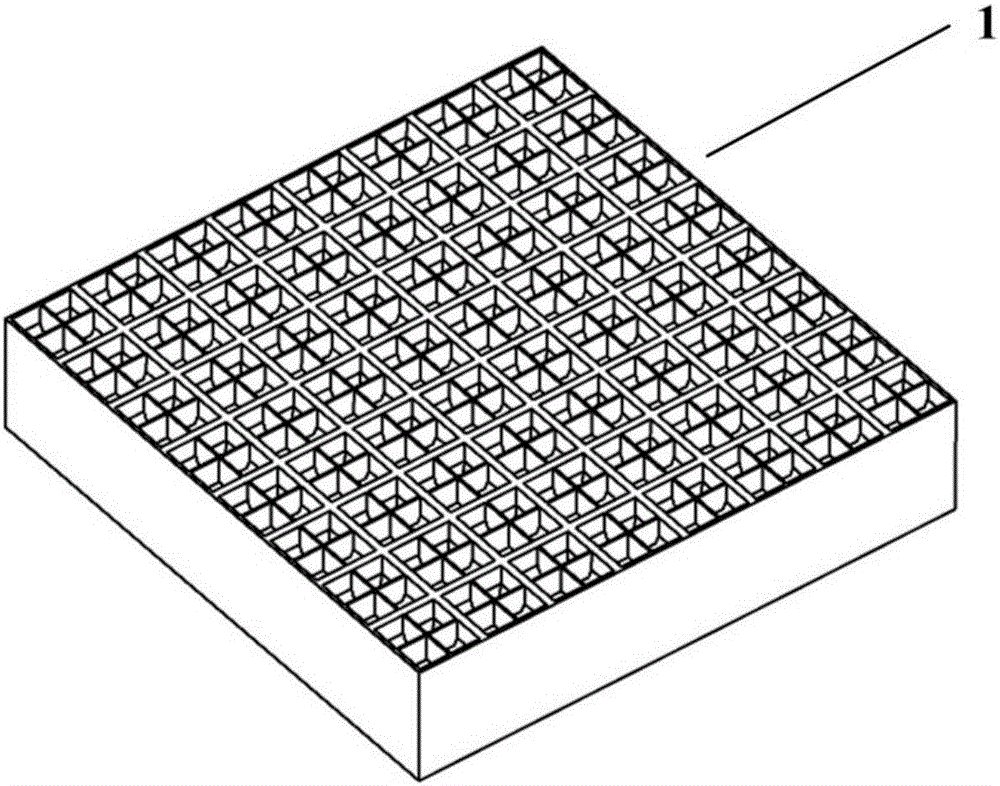
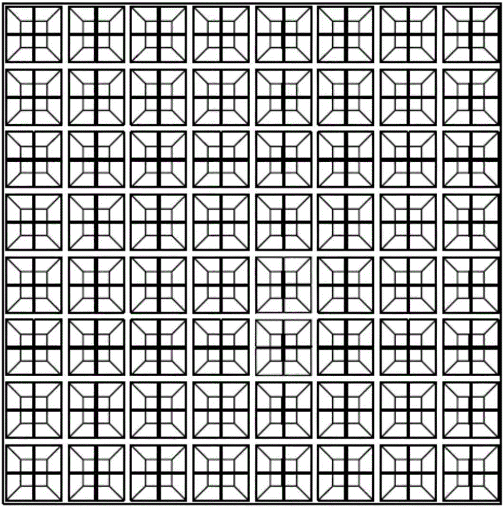
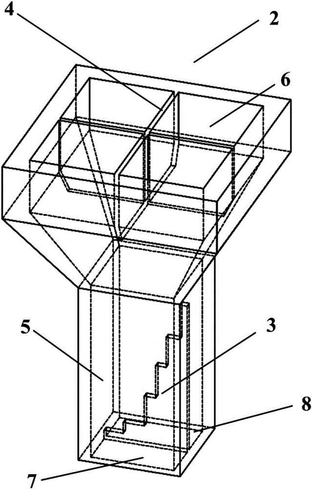
[0025] refer to Figure 1 to Figure 6 , a wide-band dual circularly polarized panel array antenna 1 with large spacing and low grating lobes, composed of m×n dual circularly polarized antenna units 2, where m and n are both natural numbers greater than 1. The dual circularly polarized antenna unit 2 includes a dual-polarized radiation cavity 5, a circularly polarized partition phase shifter 3, a grating lobe suppression partition 4, an antenna radiation port 6, a left-handed circularly polarized feed port 7 and a right-handed circular polarization Polarized feed port 8;

[0026] Circular polarization partition phase shifter 3 is a stepped metal partition, located on the centerline of the sidewall of dual polarization radiation chamber 5, the bottom edge of circular polarization partition phase shifter 3 is in contact with the dual polarization radiation The feeding port faces ...


PUM


Abstract

The invention discloses a double circularly polarized antenna unit and a large-space low-grating lobe panel array antenna. The array antenna comprises the double circularly polarized antenna unit and a feed network, wherein the double circularly polarized antenna unit comprises a dual-polarized radiation cavity, a circularly polarized diaphragm phase shifter, a grating lobe inhibition diaphragm, an antenna radiation opening, a left-handed circular polarization feed port and a right-handed circular polarization feed port, and is connected with the left-handed circular polarization feed port and the right-handed circular polarization feed port through the feed network of a dual-layer microstrip or a double-layer waveguide respectively to form a sum beam signal. A cross metal diaphragm is loaded at the antenna radiation opening, so that a good grating lobe inhibition effect can be achieved. The large-space low-grating lobe panel array antenna can be applied to antennas, which are relatively high in gain, common in receiving and transmitting and high in directionality, of a radar, communication, navigation and the like, is a low-grating lobe double circularly polarized array antenna with high efficiency under a large element space, can be used as a single-receiving, single-transmitting or receiving and transmitting array, and can also be applied to a circularly polarized phased-array antenna for electron beam scanning through expansion.

Description

technical field [0001] The field related to the design of the present invention is the field of electronic information, which can be used in radar, communication, measurement and control and other fixed beam antennas with high gain, dual polarization sharing and strong directivity. It is a high-efficiency large spacing, low grating lobe, Broadband dual circularly polarized array antenna, by extension, can also be used for electronic beam scanning circularly polarized phased array antenna. Background technique [0002] In electronic information systems, there are many ways for traditional arrays to achieve large spacing and low grating lobes, but each antenna form has its own characteristics, advantages and disadvantages, and the specific characteristics are as follows: [0003] 1. Large-pitch non-periodic arrangement array. Use large-diameter antenna elements for aperiodic array formation, and align the zero depth of the antenna element lobe with the grating lobe position o...

Claims


Application Information

Patent Timeline
IPC IPC(8): H01Q1/36H01Q3/32H01Q21/00
CPCH01Q1/36H01Q3/32H01Q21/00
Inventor 韩国栋张立军邹火儿
Owner NO 54 INST OF CHINA ELECTRONICS SCI & TECH GRP
Why Eureka
Try Eureka