Internal combustion engine tail gas utilization heat energy power system based on adjustable-pressure and stable-pressure condensation

A power system and internal combustion engine technology, applied in the direction of machines/engines, mechanical equipment, steam engine devices, etc., can solve the problems of low external waste heat absorption rate, low mechanical energy efficiency, and unstable gasification temperature of working fluid, etc., to improve gasification efficiency and condensation efficiency, stable gasification temperature and working medium flow rate, and avoiding the effect of unstable turbine speed

Inactive Publication Date: 2016-12-14
郭远军
View PDF0 Cites 3 Cited by
  • Summary
  • Abstract
  • Description
  • Claims
  • Application Information

AI Technical Summary

Problems solved by technology

[0007] However, the common problems of existing thermal power generation equipment are: a. The temperature requirements for high-temperature heat sources are high, generally above 200°C, and the thermal energy conversion efficiency is low. The thermal energy conversion efficiency is generally 15% to 35%. Under the heat source of ℃, the average thermal energy conversion efficiency is 18%; b. The gasification temperature of the working fluid is unstable, and the condensation effect of the working fluid is not good. Causes the phenomenon of high energy consumption for gasification heating; c. The driving force of the turbine is small, and the efficiency of converting the gasification substance into mechanical energy is low; d. The turbine speed is unstable, and it is prone to jamming; e. Heat collection The heat collection effect of the device is not good, and the external waste heat absorption rate is small. f. The heat displacement of the condensing device is large, and the waste of heat energy is large. The condensation speed of the natural condensation method is slow, and the active condensation method (fan air cooling or liquid pump water cooling) requires additional power consumption; g. The working fluid is easy to deteriorate or appear impurities; f. The turbine is prone to leakage of working fluid
[0008] On the other hand, the thermal energy conversion efficiency of the existing internal combustion engine is about 45%, and the exhaust temperature of the internal combustion engine exhaust gas can be as high as 400°C, and there is a large energy waste in the exhaust emission.

Method used


Image

  • Internal combustion engine tail gas utilization heat energy power system based on adjustable-pressure and stable-pressure condensation
  • Internal combustion engine tail gas utilization heat energy power system based on adjustable-pressure and stable-pressure condensation
  • Internal combustion engine tail gas utilization heat energy power system based on adjustable-pressure and stable-pressure condensation

Examples


Embodiment 1

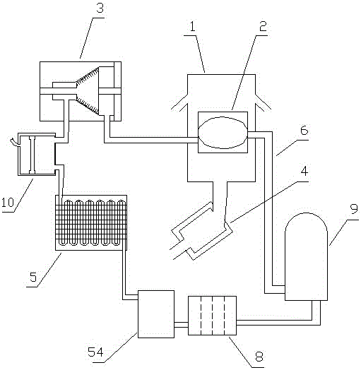
[0082] Embodiment one (such as figure 1 Shown): a power system based on adjustable pressure and stable pressure condensation of internal combustion engine tail gas utilizing heat energy, including a heat collector 1, a gasification device 2, a turbine 3, an internal combustion engine exhaust pipe 4, a condensation device 5, a circulation pipeline 6, and a circulation work The mass 7 and the one-way hydraulic pump 9, the gasification device 2, the turbine 3, the condensing device 5 and the one-way hydraulic pump 9 realize circulation communication through the circulation pipeline 6 in sequence, and the circulation pipeline 6 contains the circulating working fluid 7, and the heat collection device 1 is installed Outside the gasification device 2, the condensing device 5 includes a condensing pipe 51;

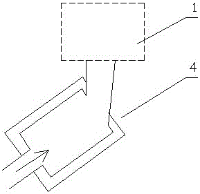
[0083] (Such as figure 2 As shown) the exhaust pipe 4 of the internal combustion engine is connected to the heat collector 1;

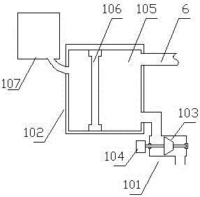
[0084] (Such as image 3 , Figure 4 shown), a...

Embodiment 2

[0097] Embodiment two (such as Figure 9 shown): The difference from Embodiment 1 is that two layers of upper cover protruding rings 111 are distributed on the lower part of the upper cover 11 of the heat collecting device 1, and two layers of lower cover protruding rings are distributed on the upper part of the lower cover 12 of the heat collecting device 1. The ring 121, the upper cover protruding ring 111 and the lower cover protruding ring 121 are staggered.

[0098] By conducting experiments on the internal combustion engine tail gas utilization heat energy power system based on adjustable pressure and stable pressure condensation in the above-mentioned embodiment 2, exhaust gas of different temperatures is discharged into the heat collector 1, the exhaust gas displacement is 1.5L / s, and the working medium in the circulation pipe The flow rate is adjusted according to the operation stability of the internal combustion engine exhaust gas utilization heat energy power syste...

Embodiment 3

[0099] Embodiment three (such as Figure 10 Shown): The difference from Embodiment 1 is that the lower part of the upper cover 11 of the heat collecting device 1 is provided with a three-layer upper cover protruding ring 111, and the upper part of the lower cover 12 of the heat collecting device 1 is distributed with a three-layer lower cover protruding ring 121 , the upper cover protruding ring 111 and the lower cover protruding ring 121 are staggered.

[0100] By conducting experiments on the internal combustion engine tail gas utilization heat energy power system based on adjustable pressure and stable pressure condensation in the above-mentioned embodiment three, exhaust gas at different temperatures is discharged into the heat collector 1, the exhaust gas displacement is 1.5L / s, and the working medium in the circulation tube The flow rate is adjusted according to the operation stability of the internal combustion engine exhaust gas utilization heat energy power system bas...


PUM


Abstract

The invention discloses an internal combustion engine tail gas utilization heat energy power system based on adjustable-pressure and stable-pressure condensation. The system comprises a gasifying device, a turbine, a condensation device and a one-way hydraulic pump for realizing circular communication through circulating pipes in sequence; circulating working mediums are in the circulating pipes; a heat collecting device is mounted at the external of the gasifying device, and is communicated with an internal combustion engine tail gas pipe; a working medium adjuster is arranged between the turbine and the condensation device, and includes a turbine current limiter and a pressure stabilizing and controlling machine; the pressure stabilizing and controlling machine includes a slow pressure current storage cylinder, a slow pressure piston and an air pressure adjuster; the top end of the slow pressure current storage cylinder is communicated with the circulating pipes, and the bottom end of the slow pressure current storage cylinder is communicated with the air pressure adjuster; and the slow pressure piston is mounted in the slow pressure current storage cylinder. The internal combustion engine tail gas utilization heat energy power system based on adjustable-pressure and stable-pressure condensation has such advantages as high heat energy conversion efficiency, stable operation and adjustable power.

Description

technical field [0001] The invention belongs to the field of energy utilization equipment, in particular to an internal combustion engine tail gas utilizing heat energy power system based on adjustable pressure and stable pressure condensation. Background technique [0002] Energy is an important material basis for the survival and development of human society. Throughout the history of the development of human society, every major progress of human civilization is accompanied by the improvement and replacement of energy. The development and utilization of energy has greatly promoted the development of the world economy and human society. [0003] However, with the continuous development and consumption of energy, non-renewable energy sources such as petroleum, coal mines, and natural gas are gradually reduced, and energy conservation and recycling are gradually being valued. The basic content of my country's current energy strategy is: adhere to the priority of conservati...

Claims


Application Information

Patent Timeline
Patent Type & Authority Applications(China)
IPC IPC(8): F01K11/02F01K27/02
CPCF01K11/02F01K27/02
Inventor 郭远军
Owner 郭远军
Why Eureka
Try Eureka