Plasma-MAG hybrid welding method

A plasma welding and composite welding technology, applied in welding equipment, metal processing equipment, manufacturing tools, etc., can solve the problems of prolonged production cycle, incomplete weld penetration, large welding deformation, etc., to improve welding quality and meet basic needs , The effect of reducing welding deformation

Inactive Publication Date: 2017-01-04
CRRC QINGDAO SIFANG CO LTD
View PDF5 Cites 7 Cited by
  • Summary
  • Abstract
  • Description
  • Claims
  • Application Information

AI Technical Summary

Problems solved by technology

[0005] First, in view of the welding process characteristics of the traditional MAG welding method itself, in order to ensure full penetration of the frame weld, the groove angle of the weldment is required to be relatively large, generally 60° angle is selected, and a welding gap needs to be left before welding, so The heat input of MAG welding is large, the amount of filler metal is large, and the joint deformation after welding is large; in addition, the number and distribution of weld seams in the frame are large and complex, resulting in large and complicated welding deformation after welding of the frame, and flame welding is required after welding. Correction by means of mechanical or mechanical methods not only increases the processing and manufacturing costs, but also prolongs the production cycle;
[0006] Second, under the conditions of the current welding process parameters, the penetration energy of MAG welding technology is limited. For the part of the frame that can only be welded on one side, the root of the weld is not easy to penetrate, especially for T-shaped welded joints, pipes, etc. Joint types such as plate joints often have incomplete penetration defects at the root of the weld; and incomplete penetration defects at the root of the weld will cause serious stress concentration, resulting in a significant decrease in the fatigue strength of the frame welded structure, seriously affecting the driving safety and service life of the vehicle

Method used


Image

  • Plasma-MAG hybrid welding method
  • Plasma-MAG hybrid welding method
  • Plasma-MAG hybrid welding method

Examples


Embodiment Construction

[0027] In order to enable those skilled in the art to better understand the solution of the present invention, the present invention will be further described in detail below in conjunction with the accompanying drawings and specific embodiments.

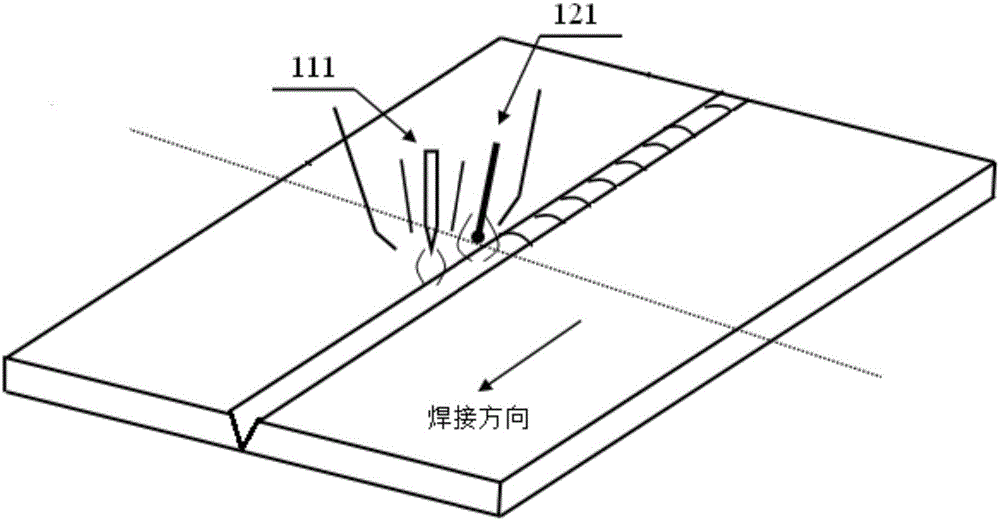
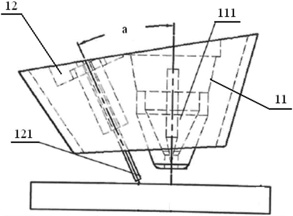
[0028] In the plasma-MAG composite welding method provided by the present invention, during welding, the plasma tungsten electrode is placed in front, and the MAG welding wire is placed behind, wherein a preset distance is maintained between the tip of the tungsten electrode and the tip of the welding wire, and the distance between the two tips of the welding piece The height of the surface is consistent; moreover, the tungsten electrode is arranged perpendicular to the welding bead, and the welding wire and the tungsten electrode form a preset angle.

[0029] As mentioned above, this hybrid welding method utilizes the characteristics of high energy density of plasma beam and strong welding penetration ability, through the keyhole ef...


PUM


Abstract

The invention discloses a plasma-MAG hybrid welding method. According to the welding method, during welding, a plasma tungsten electrode is put front, and an MAG welding wire is put back, wherein a preset distance is kept between the tip of the tungsten electrode and the tip of the welding wire, and the height from the two tips to the surface of a weldment are equal; and moreover, the tungsten electrode is perpendicular to a welding bead, and a preset included angle is formed between the welding wire and the tungsten electrode. By means of the method, the welding process is completed through interaction of two independent heat sources and the action between the compound heat sources and the weldment; the welding method has the characteristics that the weld penetration is large; the welding speed is high; heat input is low; a heat affected zone is narrow, and the welding quality is high; and the welding quality of a framework can be improved, welding deformation of the framework can be reduced, and the basic requirements for welding of the framework are met.

Description

technical field [0001] The invention relates to the field of welding technology, in particular to a plasma-MAG composite welding method. Background technique [0002] The bogie is one of the most important components of a rail vehicle. Whether its structure is reasonable or not directly affects the running quality, dynamic performance and driving safety of the rail vehicle. The frame is one of the important parts of the bogie, and it is the installation platform of each part of the bogie. It is used to connect the various parts of the bogie, transmit the force in all directions, and maintain the position of the axle on the bogie. [0003] At present, the welding of the bogie frame mainly adopts the traditional automatic or semi-automatic MAG (Metal Active Gas Arc Welding) arc welding method. [0004] The structure of the bogie frame is complex, the number of welding parts is large and the distribution is complex, and the traditional MAG welding method has the following prob...

Claims


Application Information

Patent Timeline
Patent Type & Authority Applications(China)
IPC IPC(8): B23K28/02
CPCB23K28/02
Inventor 吴向阳齐维闯张志毅陶传琦王银灵万里迟建波栾明
Owner CRRC QINGDAO SIFANG CO LTD
Why Eureka
Try Eureka