Device for preparing liquid sulfur dioxide from high-temperature sulfur-containing waste gas
A sulfur dioxide and exhaust gas technology, applied in the fields of sulfur compounds, inorganic chemistry, chemical industry, etc., can solve the problems of no recovery and utilization of flue gas, large volume of desulfurization equipment, increased system energy consumption, etc., to reduce the size of absorption equipment and improve comprehensive Efficiency, the effect of achieving separation
- Summary
- Abstract
- Description
- Claims
- Application Information
AI Technical Summary
Problems solved by technology
Method used
Image
Examples
Embodiment 1
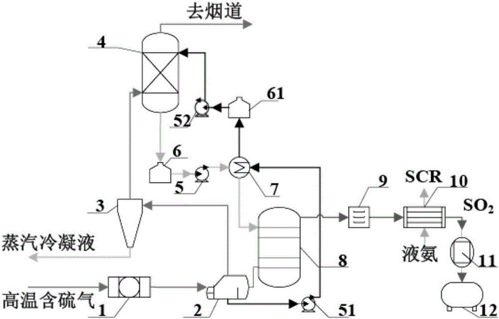
[0027] Such as figure 1 , a device for preparing liquid sulfur dioxide from high-temperature sulfur-containing waste gas, including a high-efficiency ceramic filter 1, a reboiler 2, a phase-change condenser 3, an absorption tower 4, a circulating pump, an absorption liquid storage tank, and a lean / rich liquid heat exchanger 7 , desorption tower 8, drier 9, gasification condenser 10, compressor 11 and liquid sulfur dioxide storage tank 12.
[0028] Filter 1, reboiler 2, phase change condenser 3, and absorption tower 4 are connected in sequence to form a high-temperature sulfur-containing gas passage. The absorption tower 4, the absorption liquid storage tank 6, the circulation pump 5, the lean / rich liquid heat exchanger 7, and the desorption tower 8 are connected in sequence to form a rich liquid passage. The desorption tower 8, reboiler 2, high temperature circulation pump 51, lean / rich liquid heat exchanger 7, absorption liquid storage tank 61, circulation pump 52, and absor...
Embodiment 2
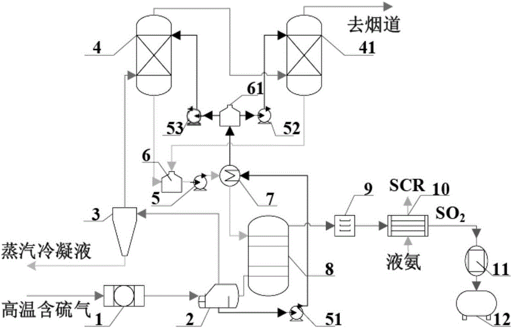
[0033] Such as figure 2 As shown, the absorption tower adopts a two-stage series structure, that is, the absorption tower 4 and the absorption tower 41 are connected in series. The two absorption towers are respectively connected to an absorption liquid storage tank 6, and are connected to a lean / rich liquid heat exchanger 7 through a circulation pump 5, and the lean / rich liquid heat exchanger 7 is connected to a desorption tower 8 to form a rich liquid passage. The reboiler 2 is connected to the lean / rich liquid heat exchanger 7 through the circulation pump 51, and the lean / rich liquid heat exchanger 7 is connected to the absorption liquid storage tank 61 and respectively connected to the absorption tower through two circulation pumps (circulation pump 52 and circulation pump 53) 4 and absorption tower 41. The sulfur dioxide content in the tail gas is lower than 20mg / Nm 3 . All the other structures are with embodiment 1.
Embodiment 3
[0035] In Embodiment 1, the ammonia gas coming out of the vaporization condenser 10 is returned to the refrigeration section for liquefaction and then recycled. All the other structures are with embodiment 1.
PUM
 Abstract
Description
Claims
Application Information
 - R&D
- Intellectual Property
- Life Sciences
- Materials
- Tech Scout
- Unparalleled Data Quality
- Higher Quality Content
- 60% Fewer Hallucinations
Browse by: Latest US Patents, China's latest patents, Technical Efficacy Thesaurus, Application Domain, Technology Topic, Popular Technical Reports.
© 2025 PatSnap. All rights reserved.Legal|Privacy policy|Modern Slavery Act Transparency Statement|Sitemap|About US| Contact US: help@patsnap.com


