A current detection unit leakage current elimination circuit and elimination method

A current detection unit, a technology for eliminating circuits, applied in the direction of measuring current/voltage, measuring only current, measuring devices, etc., to avoid leakage current, improve accuracy, and low cost

Active Publication Date: 2019-03-26
THE 41ST INST OF CHINA ELECTRONICS TECH GRP
View PDF9 Cites 0 Cited by
  • Summary
  • Abstract
  • Description
  • Claims
  • Application Information

AI Technical Summary

Problems solved by technology

[0007] Aiming at the above-mentioned technical problems existing in the prior art, the present invention proposes a current detection unit leakage current elimination circuit and elimination method, which is reasonably designed, overcomes the deficiencies of the prior art, and solves the leakage current problem existing in measuring instruments and meters , which improves the detection accuracy of weak current and has good promotion value

Method used


Image

  • A current detection unit leakage current elimination circuit and elimination method

Examples


Embodiment 1

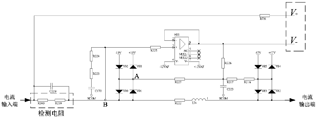
[0030] Such as figure 1 A current detection unit leakage current elimination circuit shown, including a resistor, a capacitor, an inductor, a diode and an operational amplifier;

[0031] The resistors include a first resistor R216, a second resistor R217, a third resistor R222, a fourth resistor R223, a fifth resistor R224, a sixth resistor R225, a seventh resistor R226, an eighth resistor R227, a ninth resistor R239, a Ten resistors R240 and eleventh resistors R701;

[0032] The capacitors include a first capacitor C170, a second capacitor C223 and a third capacitor C229;

[0033] The diodes include a first diode V82, a second diode V83, a third diode V84, a fourth diode V85, a fifth diode V90, a sixth diode V91, and a seventh diode Tube V92 and eighth diode V93;

[0034] The ninth resistor R239 and the tenth resistor R240 are connected through a line to form a detection resistor; the tenth resistor R240, the ninth resistor R239, the third resistor R222 and the inductance ...

Embodiment 2

[0039] On the basis of the above embodiments, the present invention also mentions a method for eliminating the leakage current of the current detection unit, which is used to eliminate the leakage current of the current detection unit, including the following steps:

[0040] Step 1: Set the common terminal formed by the anode of the eighth diode and the cathode of the sixth diode as point A;

[0041] Step 2: Set the common terminal formed by the third resistor and the ninth resistor as point B;

[0042] Step 3: follow the potential of point B to the potential of point A through the operational amplifier;

[0043] Step 4: During PCB layout, lead a metal ring from point A to protect the detection circuit and isolate the detection circuit from nearby circuits;

[0044] Step 5: Eliminate leakage current.

[0045] suppose figure 1 The potential of point B in the middle is V, assuming that the resistance of the insulating material of the surrounding adjacent circuit is R, and the...


PUM


Abstract

The present invention discloses a current detection unit leakage current elimination circuit and a current detection unit leakage current elimination method, and belongs to the current detection field. The current detection unit leakage current elimination circuit comprises resistors, capacitors, inductors, diodes and an operational amplifier. According to the present invention, the accurate, low-noise and low-bias current operational amplifier follows a detection signal voltage circuit to form an equipotential protection circuit, the equipotential low impedance output is generated as a protection signal, and at the PCB layout, a metal protection ring is added in a high impedance signal detection access, so that the isolation protection of the detection access and a nearby circuit is realized, a leakage current caused by the potential difference of the detection access and the nearby circuit is avoided, a current detection unit leakage current elimination purpose is achieved, the weak current detection accuracy is improved, and the PCB space is utilized fully. The circuit can realize the weak current-to-voltage conversion accurately, finishes a current detection function, is simple in structure and low in cost, and has a good application value in the relevant measurement fields, such as the current detection, etc.

Description

technical field [0001] The invention belongs to the field of current detection, and in particular relates to a current detection unit leakage current elimination circuit and an elimination method. Background technique [0002] In recent years, economic prosperity and rapid development of science and technology have greatly promoted technological innovation in military, communication, medical, biological, chemical and other fields, especially electronic measurement technology. Electronic measurement technology widely exists in real life, such as the measurement of temperature, humidity, light, sound, force and so on. For these common physical quantities in life, the field of electronic measurement technology usually converts them into voltage or current signals for processing by sensors. [0003] Voltage and current signals are the research objects in the field of electronic measurement technology and instrumentation, and are inseparable from the development of modern scienc...

Claims


Application Information

Patent Timeline
Patent Type & Authority Patents(China)
IPC IPC(8): G01R15/00G01R19/00
CPCG01R15/00G01R19/0092
Inventor 张根苗李斌张永坡王文廷王俊王群
Owner THE 41ST INST OF CHINA ELECTRONICS TECH GRP
Why Eureka
Try Eureka